Yaskawa J50M Instructions User Manual
Page 54
2.9.19 TOOL RADIUS COMPENSATION C
(G40, G41, G42)
t
(Cent’d)
F.
G.
H.
I.
J.
L.
An input error occurs if a G code,
to
of plane designation for changing the
compensation plane is programmed during
compensation.
Program circle cutting
, and
canned cycles
G74, G76, G77, G80
to G89) in the tool radius compensation
cancel mode.
Circle cutting and helical
cutting incorporate tool radius compensat-
ing functions in themselves.
Input error
when
are
‘n
compensation mode.
Tool radius compensation C is also possible on
circular interpolation by radius designation.
Subprogram
M99) can be programmed in
compensation mode.
Compensation is applied to the projection to
the compensation plane designated by
G18 or G19 when simultaneous movement
along three axes (four
maximum) is pro-
grammed in compensation mode.
POSITION
OF PULSE DISTRIBU-
TION OUT OF THE
COMPENSATION PLANE .
COMPENSATION
‘
L
A
N
E
I
-
”
*
2.49
Input error
when circular in
-
terpolation is programmed out of the plane
designated by
G18 or G19.
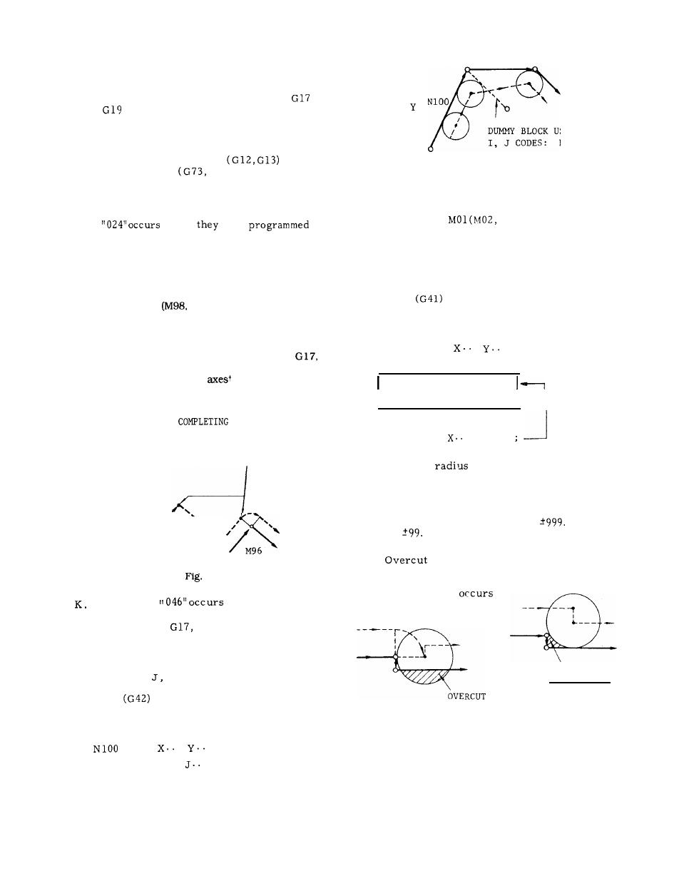
Offset position may be temporarily modified
by programming a dummy block using ad-
dresses I,
K.
GO1
.
. ;
N101
I , . .
. ;
M.
N102
‘\
--
.
N1OO
f
L
/
DUMMY BLOCK USING
I, J
CODES:
N101
x
Fig. 2.50
Advance reading of blocks is prohibited
when MOO,
M30) commands are
given, and compensation is usually inter-
r u p t e d .
Continuation of correct compen-
sation is secured by programming 1, J, K
in a dummy block immediately before MOO,
MO1 to avoid interruption.
N200 GO1
.
. ;
N201
I . . .
J.. .
;
Command
I
N202
MOO ;
1
I
movement
data N203
N .
o .
using I, J
N203
. Y.. .
Up to
99
values can be stored in the
offset memory in total for the tool radius
compensation , together with the values for
other compensation.
Make designation by
a D code.
The maximum programmable value
of tool radius compensation is
999 mm
(or
9999
inch) .
occurs if compensation is program-
med on a step less than the too! radius in
M96 mode.
Keep this in mind. Although
undersize cut
with the G97 mode , it
is better than overcut with the M96 mode.
UNDERSIZE
CUT
(a)
M96 mode
(b) M97 mode
Fig. 2.51
N102
x . . .
46