14 high-speed contouring function* i – Yaskawa J50M Instructions User Manual
Page 135
(i) The tool moves in sequence of O
A B + C
(D) .
(ii) The speed between O
A is as commanded (F
command * override)
A C is the variable speed zone.
(iii) Speed variation curve
F
(
SPEED
)
1
L
A
(B)
c
(MOVE DISTANCE)
F i g .
2.85
Fo = (Commanded feedrate) * (Override
= Fo * (#6216) . . . (given as n% of Fo)
= Fo * (#6217) . . . (given as
of Fo)
(iv) Speed change positions
(3) Notes
(a) Corner override can be calculated to a single
position. If corner override is commanded in a
2-axis simultaneous command, the override
automatically changes to the I or J direction at the
commanded position.
(b) Command the G codes of group 01 when the
G106 command is given. If not,
(029:
occurs.
(c) Commanding I and J simultaneously by the G106
command causes an alarm (039:
G106 X, Y, I, J).
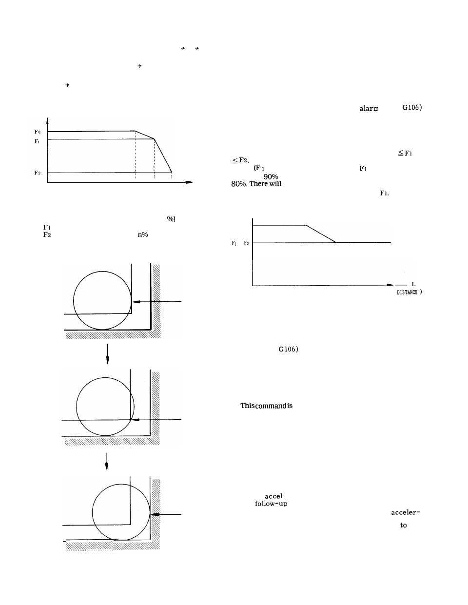
(d) When the tool radius is larger than the cutting
margin, and a mistake in setting is made to be Fo
the speed is clamped at the value immediately
before
against F2). For example, if
is set at 80%
and F2 at
by mistake, calculation is made with F2 as
thus be no automatic corner override
between A and B, and the speed is clamped at
F
(
SPEED
)
=
(MOVE
POINT A
F i g .
2.87
(e) Set #6216, #6217 between 1 and 100. (Do not
set “O.”)
(f) Commanding G106 in a canned cycle causes
alarm (029:
.
(g) Alarm (039:
G106X, Y, I, J) occurs when no
I or J command is found against the move axis in
the G 106 block.
(h) No override is performed by the G106 command,
if the tool radius is 1 / 2 or less the cutting margin.
(i)
valid during the radius compensation.
POINT B
2.14 HIGH-SPEED CONTOURING FUNCTION*
I
2.14.1 OVERVIEW
Form compensation function
Generally, when contour cutting is commanded, the
orbit shifts (sagging or shrinking arc radius at the
corner) because of the time delay of the exponential
function
I decel, or by the influence of the
servo
delay.
POINT C (D)
So the linear interpolation with linear
ation ( G 198) and linear interpolation with linear
deceleration (G 199) are developed and added
the
/
preparatory y functions.
This limits the acceleration
in case the speed variation is too radical since it
may shock the machine.
Fig.
2.86
127