Yaskawa J50M Instructions User Manual
Page 177
5.1.15 MANUAL REFERENCE POINT RETURN SWITCH
t
This switch is for bringing the tool back to the reference
point manually.
For its operation method, refer to 5.2.1 “MANUAL
RETURN TO REFERENCE POINT’.
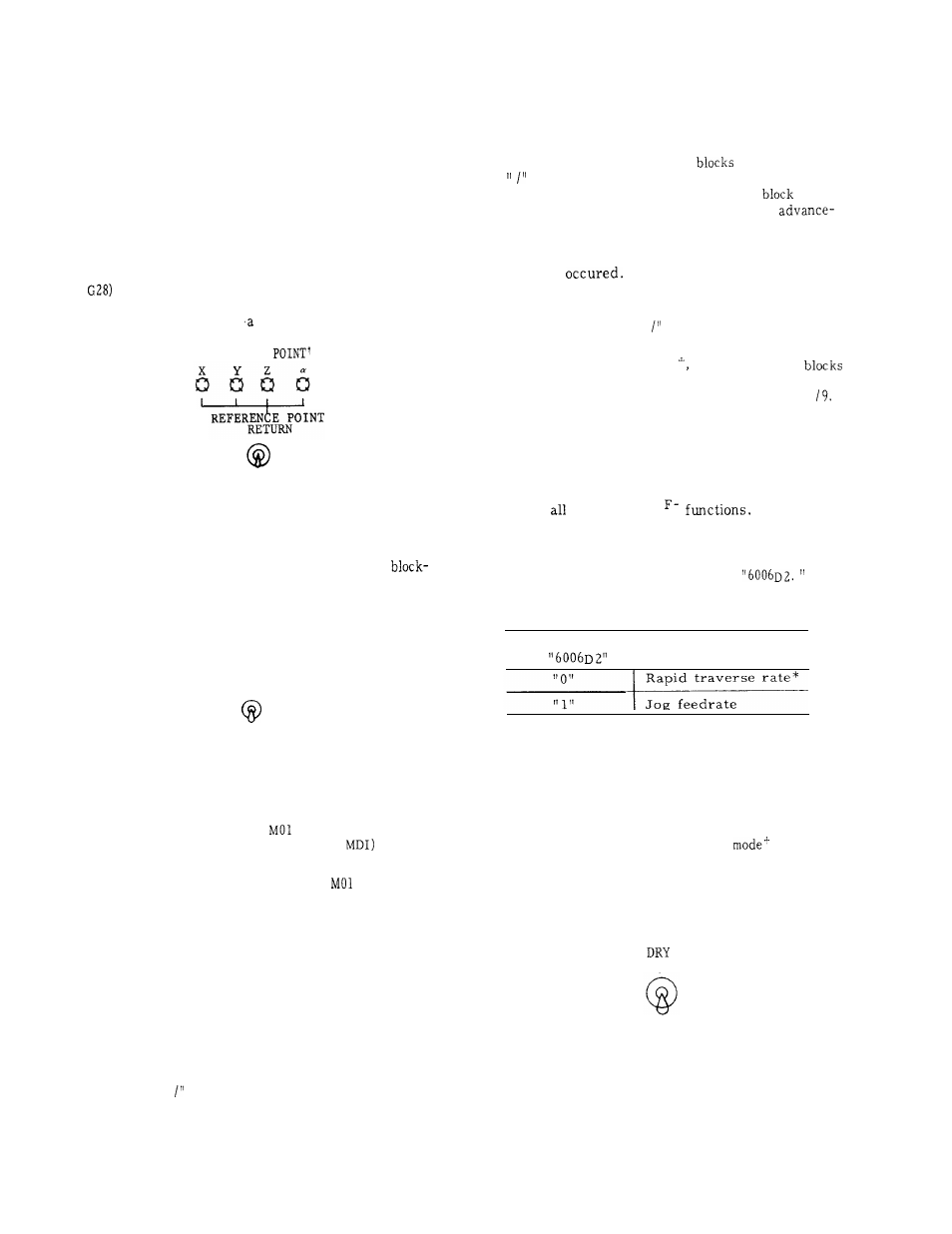
5.1.16 REFERENCE POINT LAMPS
t
These lamps indicate that the tool is positioned
on the reference point.
They light when the tool
is brought to the reference point through the
manual or automatic return to reference point
(
, or by the reference point return check
( G27) , and goes out as the tool moves away from
the reference point by subsequent operation.
REFERENCE
OFF
Fig. 5.10
5.1.17 SINGLE BLOCK SWITCH
Turning on this switch permits individual
by-block operation.
Turning on this switch after
finishing the current block in the automatic oper-
ation mode, the machine stops. A block of data
is executed each time the CYCLE START push-
button is activated.
SINGLE
BLOCK
OFF
Fig. 5.11
5.1.18
OPTIONAL STOP SWITCH
This switch is to execute
command in auto-
matic operation mode (TAPE, MEM or
.
When the switch is on , the program stops on
completion of the block including
command,
while CYCLE START pushbutton remains illu-
minated.
When the control catches FIN signal,
the light is extinguished. To restart the pro-
gram, depress the CYCLE START button.
When the switch is off, MO1 command is ignored.
Operation of the switch is not effective for the
block being executed.
During the automatic op-
eration, the switch acts for the next block.
5.1.19 OPTIONAL BLOCK SKIP SWITCH
1.
While the switch is on, all the commands in
a block programmed after a “/“ are neglected.
However, block data appearing before the
“ /“ remains effective.
2.
While this switch is off,
including a
are executed along with other blocks.
This switch is ineffective on the
under
execution and blocks stored in the
reading buffer .
When this switch is turned
on during an automatic operation cycle , it
works on the block read after the switching
on has
Notes :
a.
The two commands “ and “ /1” are equivalent.
b.
With the control provided with the optional
block skip B function 8 independent
can be skipped with the switching of the
switches corresponding to “ /2” through “
“
5.1.20 DRY RUN SWITCH
Turning on the DRY RUN switch in the TAPE,
MD I or MEM mode causes the tool to move at the
speed selected by the JOG FEEDRATE switch,
ignoring
programmed
F com-
mands can be displayed as they are programmed.
This switch may be used to check the program .
Rapid traverse ( GOO) rate for dry run operation
can be set by setting parameter #
Table 5.5
Parameter
I
Rapid Traverse at
#
Dry Run Operation
* The tool moves at the traverse rate
set by RAPID TRAVERSE RATE
OVERRIDE switch if provided.
Notes :
Switching
the DRY RUN switch during auto-
matic operation becomes effective on the current
block .
Switching it in mm /rev
or during
tapping becomes effective on the next block.
During tapping , the set speed when tapping
starts will be kept.
It cannot be changed by
JOG operation during dry run operation .
RUN
OFF
Fig. 5.12
This switch selects whether the data in blocks
including a “ is disregarded or not.
169