Yaskawa J50M Instructions User Manual
Page 184
5.2.1.3 EASY REFERENCE POINT RETURN t (Cent’d)
(EXAMPLE)
When the setting value of the final run
distance is negative and the distance
exceeded the distance from the deceler-
ation limit switch to the theoretical
C-phase pulse.
5.2.2
AUTOMATIC COORDINATE SYSTEM
With this function, a new coordinate system is
set up automatically upon the return of the tool
to the reference point by the manual reference
point return function.
The coordinates of the
new origin are preset with the following param-
eters.
The coordinate system set up
this
function is equivalent to the ones set up by G92.
1.
Parameters for metric input system
Parameter
#6636
#6637
#6638
#6639
Meaning
X coordinate
Y coordinate
Z
coordinate
4th coordinate
Parameters for inch input system
Parameter
Meaning
#6630
X coordinate
#663 1
Y coordinate
#6632
Z
coordinate
#6633
4th coordinate
3.
Axis can be selected by parameter #6015 for
both metric and inch systems.
5.2.3
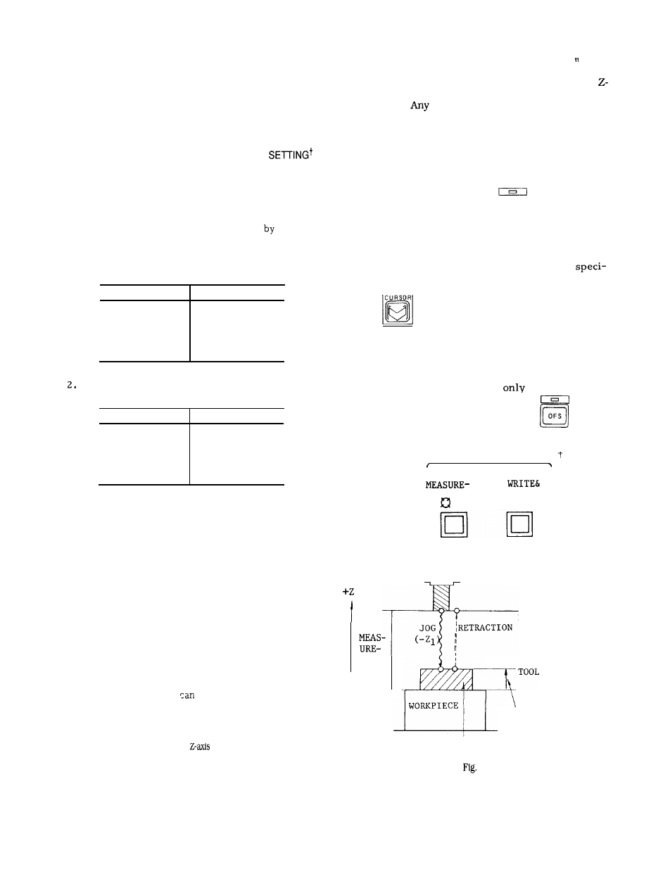
TOOL LENGTH Measurement
When a tool mounted on the spindle is manually
brought to a position where the tool tip makes
contact with the reference surface for Z-axis,
. .
and the WRITE & RETRACT button is pushed,
the following operations are performed by the
control.
a.
b .
c.
The distance between the set Z-axis home
position and the reference surface is stored
automatically in the memory having the cur-
rently specified correction number.
The difference between tool touch position
and base position
be set by parameter.
1. Measuring method (parameter #6039D4 = O“ )
a.
b.
c.
d.
e.
Mount a tool on the spindle, and move it to a
axis position which is to be set as the reference
point.
position may be set as the reference
point, but for facilitating tool changing process, the
tool changing position may be set up as the refer-
ence point.
Select the manual operation mode (RAPID,
JOG, HANDLE or STEP) using MODE SE-
LECT switch.
Depress the function key
❑
OF S .
The offset number’ specified previously and
related data are displayed.
The page covering tool offset values
fied the tool offset number keyed in will be
shown.
The specified number is shown by
CURSOR
Depress the MEASUREMENT button when the
motion stops. MEASUREMENT lamp lights and
the current position of Z-axis will be set as home
position.
(The button is effective
in the manual
operation mode and while the
key is
OF S
selected. )
TOOL LENGTH MEASUREMENT
MENT
RETRACT
MOVE
MENT
(ML)
R E F E R E N C E P O I N T
JOG
/
R E T R A
C
T
I O N
BASE
Increase the correction number by 1, in pre-
paration for the next writing.
Return the tool to the
home position.
BLOCK GAGE
5.27
TOUCH POSITION
POSITION (B)
TOOL
LENGTH
M E A S U R E M E N T
SETTING #65 07
176