Yaskawa J50M Instructions User Manual
Page 245
X - a x i s
Y–axi s
Z - a x i s
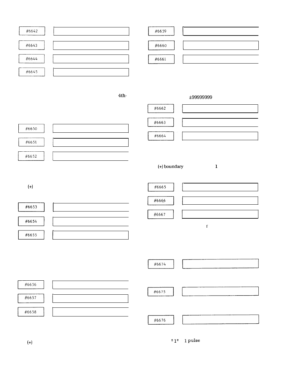
4 t h a x i s
# 6 6 4 2 t o # 6 6 4 5 :
Specifies
the compensation interval in pitch error
compensation, respectively, on the X-, Y-, Z and
axes.
Setting : “ 1“ = 1 pulse
Setting range : 0 to *99999999
X–axis
Y–axis
Z–axi s
1
#6650 to #6652 (optional) :
Specifies stored stroke limit 3 for X-, Y-, and Z-axis,
respectively.
Plus
boundary setting : “ 1“ = 1 pulse
Setting range : 0 to *99999999
X-axis
Y-axis
Z–axis
#6653 to #6655 (optional) :
Specifies stored stroke limit 3 for X-, Y-, and Z-axis,
respectively.
Minus (-) boundary setting : “ 1” = 1 pulse
Setting range : 0 to *99999999
X - a x i s
Y – a x i s
Z – a x i s
#6656 to #6658 (optional) :
Specifies stored stroke limit 4 for X-, Y-, and Z-axis,
respectively.
Plus
boundary setting : “ 1“ = 1 pulse
Setting range : 0 to *99999999
X - a x i s
Y – a x i s
Z–axis
I
#6659 to #6661 (optional) :
Specifies stored stroke limit 4 for X-, Y-, and
Z-axis,
respectively.
Minus (-) boundary setting : “ 1” = 1 pulse
Setting range : 0 to
X – a x i s
Y – a x i s
Z-axis
#6662 to #6664
(optional) :
Specifies stored stroke limit 5 for X-, Y-, and Z-axis,
respectively.
Plus
setting : “ 1“ = pulse
Setting range : 0 to *99999999
X–axis
Y – a x i s
Z–axis
#6665 to #6667
(optional)
Specifies stored stroke limit 5 for X-, Y-, and
respectively.
Minus (-) boundary setting : “1” = 1 pulse
Setting range : 0 to *99999999
z-axis,
Sets the multiplication factor of characters of the
display at power on.
Sets the CRT starting position of the title display at
power on.
Handle input pulse lag pulse clamp amount
Setting:
=
( i n p u t p u l s e )
237