7 tool compensation – Yaskawa J50M Instructions User Manual
Page 21
2.7 TOOL COMPENSATION
2.7.1 OUTLINE OF TOOL COMPENSATION
The tool compensation function is in the following
three modes.
. Tool length compensation
This function is for compensating the differences
in tool length, and is effective in the Z axis di-
rection,
Specified length compensation becomes
effective from the block in which G43 or G44 is
programmed together with an H code. It is
with HOO or G49.
. Tool position offset ( for simple compensation
for tool radius)
This function is for compensating for errors in
machined dimensions to be introduced by the radius
of tools. It is effective in the X, Y, and Z (4th t ) axis
directions.
It is effective only for the block in which
G45-G48 is programmed together.
. Tool radius compensation C
(for compensating
for tool radius effects with complicated machin-
ing contours)
This function is for compensating for the tool
radius effect with any given machining contours.
It is effective in X-Y , Y-Z, and Z-X planes.
It becomes effective from the moment
, or
G42 is commanded together with a D code, and
is
by G40.
Not
e :
For details of these compensations func-
tions, refer to
“ P R E P A R A T O R Y F U N C T I O N
2.7.2
TOOL OFFSET MEMORY
For the three groups of offsets, all the necessary
offset values must be stored in memory before-
hand.
The following number of offset values can be
stored in the tool offset memory.
Offset Value Storage
Basic
I
99
t Optional
I
1199
The setting range of offset values is as follows.
Linear axis
R o t a r y
Metric input
O - 999.999 mm
O- 999.999 deg
Inch input
O - 99. 9999 inch O- 999.999 deg
For the procedures of storing values into memory, refer
to 4.3.5.
“DISPLAYING AND WRITING OF TOOL OFF-
SET AND WORK
on page 144.
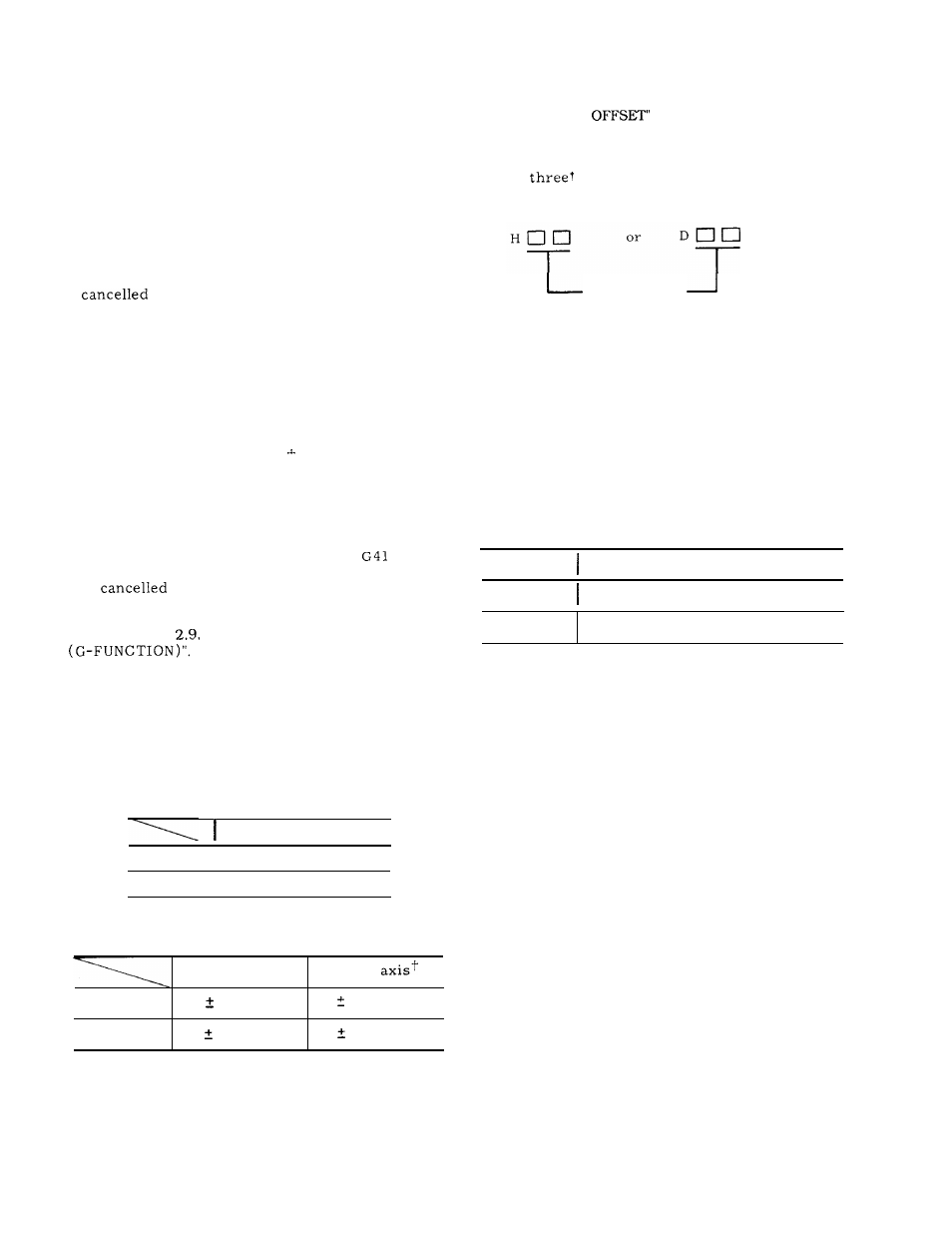
2.7.3 H- AND D-FUNCTION (H, D CODES)
Two or
digits, following the address H or
D , specify tool offset numbers.
T o o l o f f s e t
number
The tool offset numbers 01 through 99 directly
correspond to the
99
offset-value memory num-
b e r s .
That is, when certain numbers are des-
ignated, the corresponding g offset values stored
in the offset memories will be used to offset the
tools .
Tool offset numbers 00 (HOO or DOO) have differ-
ent meanings depending on the respective offset
functions.
For details, refer to the descriptions
on the respective G functions.
H- and D-codes must be used properly according
to their functions.
Code
Function
H code
Tool length offset
1
D code
Tool position offset, Tool radius
compensation
The tool offset numbers 01 through
99
can be
used freely in combination with the both H and
D codes.
Listed input values do not depend on metric/
input output system.
13