Yaskawa J50M Instructions User Manual
Page 206
7.3.4
LED (RED) LIT
351:
OL(X) . . .
X- axis overload
(1) This red LED lit when abnormal temperature rise of
the internal parts is detected.
(2) When this is because of abnormal temperature rise,
the power supply can be turned on after POWER OFF
ON.
7.4
THERMAL OVERLOAD RELAY OF
SERVO UNIT
The
servo
control unit has the function of de-
tecting the following alarm
status.
Alarm No.
Circuit protector trip
331(X) 332(Y) 333(Z)
334(4)
Overload
I
351(X) 352(Y) 353(Z)
354(4)
Servo alarm
7.4.1 CIRCUIT PROTECTOR TRIP
(ALARM NO. 331 TO 334)
When the main circuit of the servo control unit is
shorted or when the servo control unit itself be-
comes faulty, the circuit protector in the unit
will be tripped, and the following
Nos. will
be displayed on the CRT.
FUSE(X) . . .
for X-axis
332:
FUSE(Y) . . . for Y-axis
333:
FUSE(Z) . . .
for Z-axis
334:
F U S E
(4) . . . for 4th axis
When a
protector is trfpped, and the alarm No. 331
to 334 is displayed, do not attempt to take measures, but
the user should immediately notify your
representative.
7.4.2 OVERLOAD (ALARM NO. 351 TO 354)
The
servo control unit is provided with electronic
thermal relays respectively and independently for
the X and Z axes, and they trip under the follow-
ing conditions.
programs involving excessively heavy cuts
are executed.
Programs involving excessively frequent speed
changes are executed.
Frictions in the machine system become excessively
large.
352:
. . .
Y-axis overload
353:
. . .
Z-axis overload
354:
4Th axis overload
this is the
case,
take the following
measures.
( 1 )
( 2 )
(3)
( 4 )
Push the POWER OFF button
to turn off
the power supply, and then, stop the
-
ply of power to NC.
Find the cause of the overloading . For
example , the cause may be eliminated through
modifications of the part program, or by
the elimination of abnormally large load on
the machine.
Supply power to the NC, and push the
POWER ON button to turn on the power
supply and make the system ready for
operation.
However, since the servo motor
requires approximately 30 minutes to cool
down after being overloaded to the extent
of tripping the electronic thermal relay,
wait at least 30 minutes before starting to
operate NC .
If the electronic thermal relay trips, notify your
Yaskawa representative.
7.4.3 SERVO ALARM (ALARM NO. 391 TO 394)
The servo control
unit can detect the following
alarm states.
A L A R M
is
displayed on the CRT, open the door of NC unit,
confirm the LED display for each axis on the
servo control unit, and then immediately notify
your YASKAWA representative.
(2) Release the door interlock switch before
opening the door of NC
u n i t .
(3) Read the accompanying Maintenance Manual
for details.
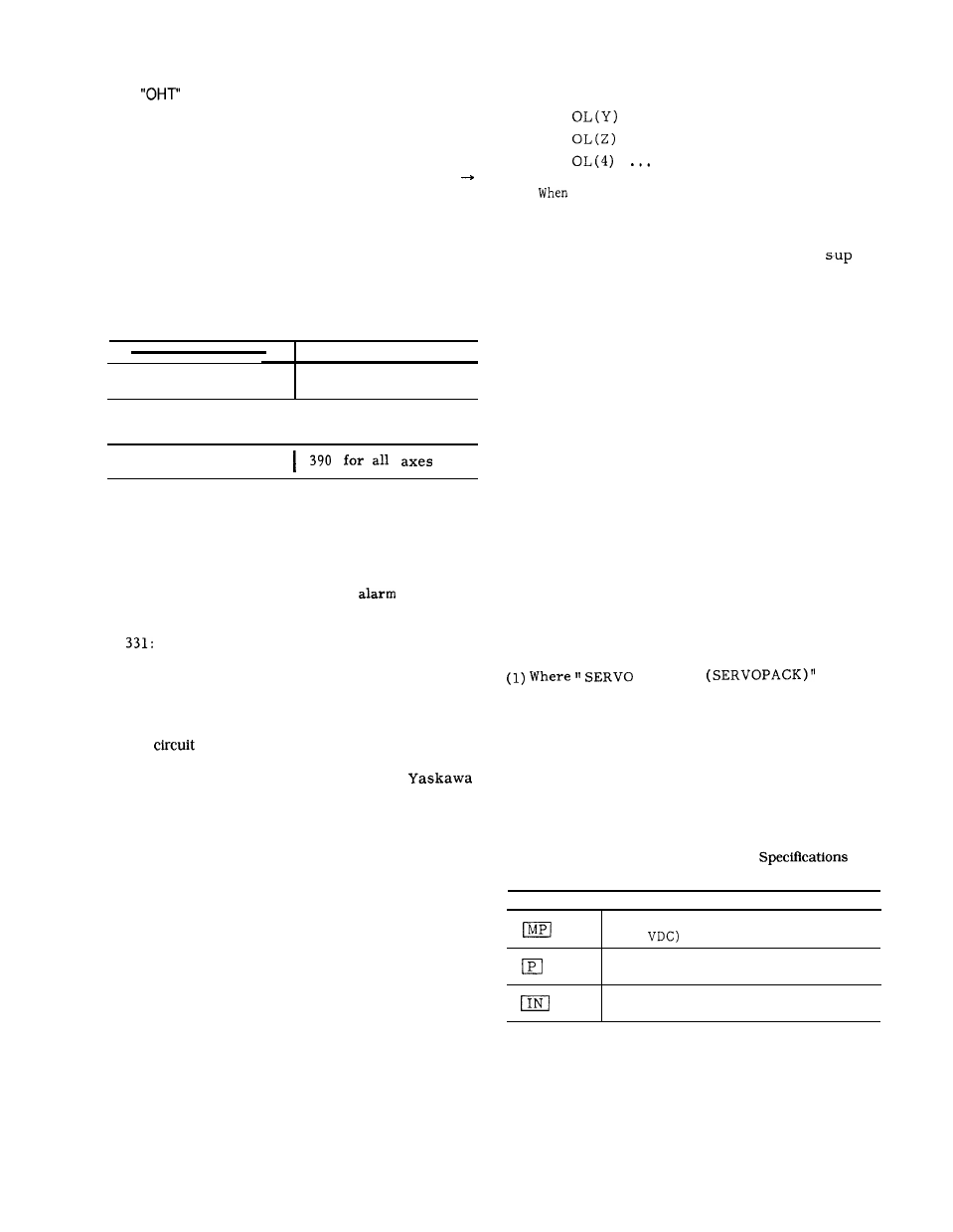
Table 7.1 Relation between Display
for
LEDs and Output Signals
LED Name I
Indications (When Lit)
Main circuit voltage (higher than
200
in Servopack is normal.
Control power supply (+5 V) in
Servopack is normal.
Speed command input (higher than
60 mV) has been applied.
When the electronic thermal relay trips, the
servo power supply is turned off, and the follow
-
ing
alarm Nos. are displayed on the CRT .
198