Yaskawa J50M Instructions User Manual
Page 229
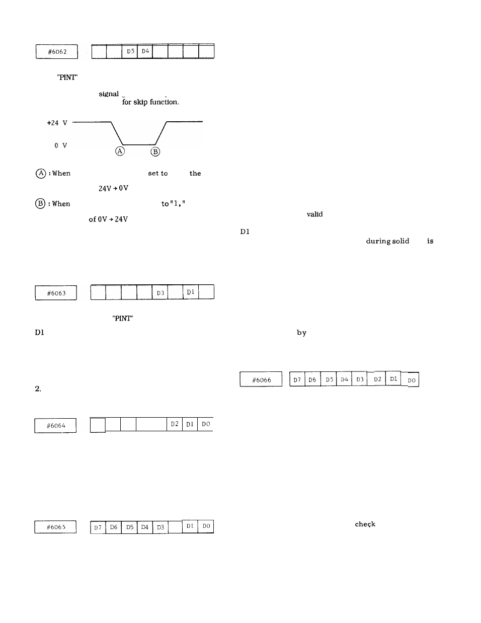
D5 :
D4 :
Sets the signal state of processing start of
input for pint function.
This sets the
state of processing start
o f “ s k i p ” i n p u t
–
this parameter is
“O,”
processing starts at the time when the
change of
occurs.
this parameter is set
the
processing starts at the time when the
c h a n g e
o c c u r s .
Notes :
1. Be sure to turn the power on and off after chang-
ing the parameter.
2.
Be sure to set “O” except in D4 and D5.
D3
D3 :
This determines the ENABLE/DISABLE of
control circuit of
input for pint function.
:
This determines the ENABLE/DISABLE of
control circuit of “SKIP input for skip function.
Notes :
1. Be sure to set “ 1” when using the skip function
and program interruption function.
Be sure to turn the power on and off after
changing the parameter to set “O” except in D 1
and D3.
I
D3
D3, D2, Dl, DO
Shown in the order of 4th-axis, Z-axis, Y-axis
and X-axis.
1:
Follow-up processing is performed during
servo-off input.
o:
Follow-up processing is not performed during
servo-off input.
D7 1:
Spindle PG is attached to the motor
(indicate the PG mount position).
o:
The spindle PG is directly linked to the
spindle.
Note :
Be sure to turn the power on and off after setting
this parameter.
D6 1:
0 :
D5 1:
0 :
D4 1:
0 :
D3 1:
0 :
New radius compensation method
Old radius compensation method
Type A compensation method
Type B compensation method
Changes type A compensation method
offset direction.
Changes type B compensation method
offset direction.
Changes offset value at the starting point.
Changes offset value at the end point.
Note : D5 to D3 are
only when #6065 = 1.
1:
The synchronous error peak value of the
spindle and the z-axis
tap
displayed.
o:
The synchronous error peak value of the
spindle and the Z-axis during solid tap is
not displayed.
(The plus peak value is displayed on the X-axis error
pulse display section, and the minus peak value is
displayed on the Z-axis error pulse display section).
DO 1:
Do not wait for PSET during the tapping
cycle
the solid tap function.
o:
Waits for PSET during the tapping cycle by
the solid tap function.
D7 1:
0 :
D6 1:
0 :
D5 1:
0 :
D4 1:
0:
D3 1:
0:
JOG speed of 4th axis is 1/10 of basic 3
axes.
JOG speed of 4th axis is not 1/10 of 3
axes.
At power on, M97.
At power on, M96.
H/D changing 150/ 150 sets.
H/D changing 100/200 sets.
With interference check function
Without interference
function
Cross point calculation automatic selection
is performed
Cross point calculation automatic selection
is not performed
221