Yaskawa J50M Instructions User Manual
Page 179
. The following M codes are executed even if the
switch is set on.
. MOO, MO1, M02, M30
Both its decoded signals and its BCD codes
are sent out to the machine .
. M90 to M99
BCD code is not sent out.
Turning on the M-FUNCTION LOCK switch
during automatic operation
becomes effective
on the block after the next block of the current
block.
5.1.24 MANUAL ABSOLUTE SWITCH
This switch specifies how manual moving amount is
processed at restart of operation when manual operation
is interrupted during automatic operation to move the
tools.
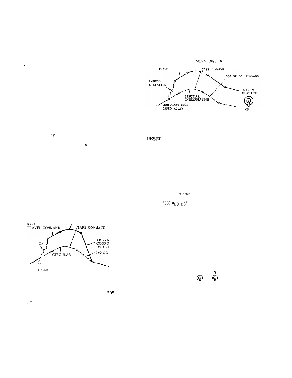
. When MANUAL ABSOLUTE SWITCH is on.
When automatic operation is restarted after in-
terrupted
manual operation , the tool per-
forms the rest of the command in the interrupted
block from the end point manual operation.
The tool moves in parallel with the path speci-
fied by the program.
When the command of the next block is GOO or
GO1, the tool moves automatically to the tar-
get coordinate specified by the program. Then
the operation is performed according to block
of data.
When the command of the next block is G02 or
G03 ( circular interpolation) , the interpolation
is performed in parallel with programmed com-
mand.
The tool automatically returns to the
target coordinate when GOO or GO1 is command-
ed after the circular interpolation.
OF
ACTUAL MOVEMENT
MANUAL
-
TRAVEL T
O
TARGET
OPERATION
COORDINATE SPECIFIED
BY PROGRAM COMMAND
GOO OR GO1 COMMAND
x
INTERPOLATION
TEMPORARY
STOP
HOLD)
Fig. 5.16
Note:
#6008 D3 can determine whether manual
absolute is ON or not in G91 mode;
--
e f f e c t i v e ,
“ 1“ -- ineffective. If #6008 is set to
9
and G91 is ineffective, next G90 makes
manual absolute effective.
When MANUAL ABSOLUTE SWITCH is off.
After the automatic operation is interrupted by
manual operation , the coordinate system is
shifted, and the tool performs the rest of the
travel commands in parallel with programmed
moves.
C O M M A N D
/
REST OF
Fig. 5,17
The parallel shift is reset by executing Reference Point
Return manually, automatically by G28, or operating the
key. The command value is forced to change to
the current position.
(a) Manual or automatic reference point return operation
(b) RESET operation
5.1.25 MIRROR IMAGE AXIS SELECTOR SWITCH
MIRROR IMAGE AXIS switch selects the axis
whose motion is reversed for programmed opera-
tions.
To select the
image axis with this switch
as well as setting function, set the data of set-
ting #
to O.
Turn on the MIRROR IMAGE
AXIS
switch of the
axis to which Mirror Image. function is assigned.
The motion of the selected mirror image axis is
set up at M95 command is given until M94 is
commanded.
For details, see 2.8.5.
Note :
During the M 95 (Mirror Image ON) mode,
never operate the MIRROR IMAGE AXIS switch,
MIRROR IMAGE
AXIS
x
OFF
OFF
Fig. 5.18
171