Yaskawa J50M Instructions User Manual
Page 68
2.9.23 WORK COORDINATE SYSTEM SETTING A
(G52 TO G59)
t
(Cent’d)
Notes :
The shift amounts for work coordinate systems
can
specified by programs with G1O com-
mands, in addition to the MD I writing. For
details , refer to 2.9.8. “ TOOL OFFSET VALUE
DESIGNATION (G1O).”
Work coordinate systems set up
G54 through
G59 are canceled by the G52 command, and the
basic coordinate system becomes effective again.
When a work coordinate system has been set up by
any of the commands G54 through G59, the selected
shift amounts can not be changed even when they
are rewritten.
The rewritten shift amounts will become effec-
tive when a new work coordinate system com-
mand is executed.
G53 commands should only be given under the
following conditions.
If these conditions are
not satisfied, the commands are regarded as
e r r o r s .
(1)
(2)
(3)
If a
The mirror image function is not used.
No canned cycle is in use and no tool com-
pensation C is in use.
If a 01 group G code is used, it is
GO1 or G60 and nothing else.
G53 command is executed with the machine
lock function on, the current value displayed
changes sequentially until the command value
corresponding to the machine lock function off
state will be displayed. If the machine lock
function is switched on and off during the ex-
ecution of G53 blocks , correct positioning can
not be achieved.
H o w e v e r , when a complete G53 block is
ed with the machine lock function off, correct
positioning is achieved as programmed, even
when the machine lock function is switched on
and off before that block.
G53 commands should be given in the G 90 mode.
If they are given in the
mode, the command
values are regarded as G 90 mode values.
When work coordinate systems are to be changed
with any one of the G54 through G59 commands,
the program should be written so that a new
coordinate system will be set up in the G90
mode and the basic coordinate system will be
reset in the G90 mode.
If a G53 command is
while the tool length
(1)
(2)
If subsequent programs are given in
incremental mode, it will cause the tool to
move by incremental amount given from
reference point as a command. (Offset
amount not considered. )
If subsequent programs are
in
absolute mode, it will
tool to
move by “absolute position plus offset
amount” given as a command.
When any one of the commands G54 through
G59 is given while the tool length
compensation or tool position, the
compensation remains effective. Generally,
when any one of the commands G54 through
G59 is to be given, the tool length
compensation or tool position offset command
should be canceled in advance.
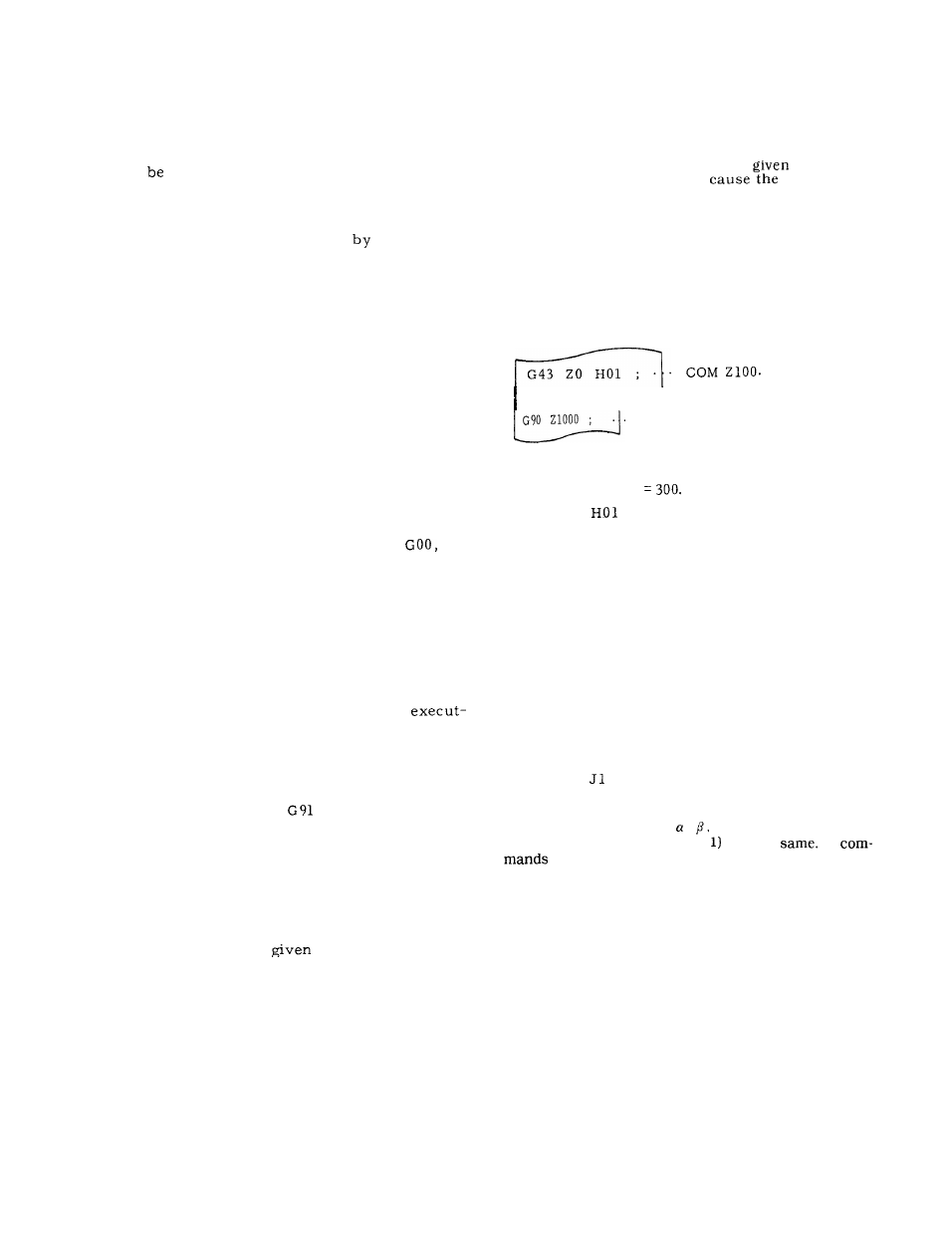
G54 ;
I
cOM “
100
’
Shift amount for Z axis is 1300.
G54 shift: Z
O f f s e t :
= 100.
. If G92 is given during execution on the work
coordinate system set up by G54 through G59,
G54 through G59 or the basic coordinate sys-
tem is shifted so that the current position is
to be a shifted position by G92, G92 should
not be used in G54 to G59 modes in general.
2.9.24
WORK COORDINATE SYSTEM SETTING B
(G52 TO G59)
t
(1) Outline of work coordinate system-setting
expansion
Up to 30 types of work coordinate systems can
be set with the expansion of the work coordinate
s y s t e m s
of specification A (6 types) by using
c o m m a n d s
to J5 at the same time as G54 to
G59. The expanded area will be set by #6700
-#6771.
The four axes X, Y, Z, ,
can be set since G54 to
G59 and G54 (J 1) to G59 (J
are the
In
J2 to J5, only three axes X, Y, Z can be set but
the 4th axis cannot be set.
(2) Setting numbers for specifying work coor-
dinate system shift
compensation or tool position offset function is
on, the tool offset value
i s d e l e t e d t e m p o -
rarily. Generally, when giving a G53 command,
the tool length compensation and tool position
offset commands should be canceled in advance.
. If a G 53 command is given while the tool
position offset command is ON, subsequent
programs will be as follows :
60