Yaskawa J50M Instructions User Manual
Page 45
These coordinate values indicate the positions
when skip signal is ON and not the position when
the tool is stopped.
These data can be treated as coordinate data in
user macros.
When a skip signal is not given in spite the exe-
cution of G31 by setting ( #6004DO) , the program
moves on to the next block automatically.
Note :
When actual skip stop detecting position is
near the skip final reference point, the dead zone
exists in the skip signal processing in the range
shown below. At this time, alarm “87 occurs when
#6004
= O. When #6004 Do = 1, the final point
value of the commanded axis is stored in #6552 to
#6555.
C
*
SKIP SIGNAL IS
(100.,50. )
A
-
INPUT HERE
N
ACTUAL MOTION
I
PATH
(80.,15. )
(Metric input)
2
7500 60 XKP
+
1 0 0 0 X 6 0 )
(Inch input)
2
7500 60 XKP
+
1 0 0 0 X 6 0 1
: Position loop gain constant (1/S)
F :
Reference speed (metric input : mm/min,
inch input : inch/rein)
2.9.19 TOOL RADIUS COMPENSATION C
(G40, G41 , G42)
t
It is possible to specify the radius of the tool and
to cause automatic tool path offset by this value.
Store the offset value (tool radius value) in the
offset value memory in advance by MDI, and pro-
gram the tool offset number correspond to the
tool radius value by a D code in the program.
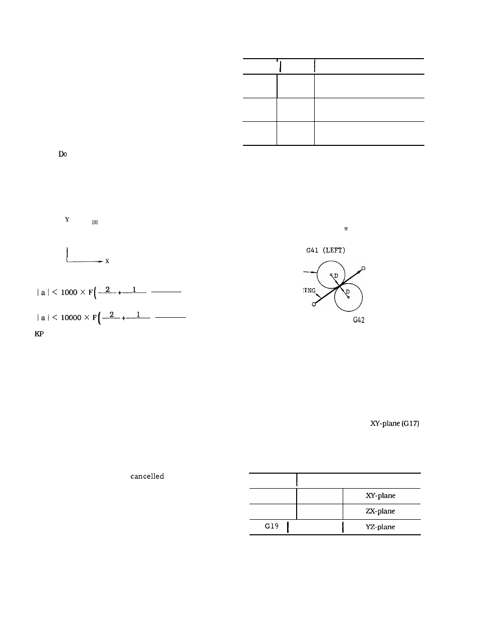
1.
Designation of compensation direction and
of D code
Tool radius compensation C is programmed
with G41, G42 and is
by G40.
G41 and G42 indicate the directions of tool
offset with respect to the direction of move-
ment.
Table 2.21 G codes of Tool Radius
Compensation C
G code Group
Meaning
G40
07
Cancellation of tool radius
compensation C
G41
07
Tool radius compensation
C , left
G42
07
Tool radius compensation
C , right
Note:
When the power is turned on, G40 is
e f f e c t i v e .
Note
that the directions of compensation
(right, left) indicated above are reversed
when the sign of the tool radius value in the
offset memory designated by a
D
code is neg-
ative.
Make sure to designate a D code in
the block containing G41, G42 or in a preced-
ing block.
If DOO is commanded, tool radius
will be regarded as “O.
TOOL
D
PROGRAMMING
(
R
I
GHT
)
Fig. 2.32
Switching between G41 and G42 can be made in
compensation mode. Details will be given in item 5
on page 40.
2.
Designation of compensating plane
The plane in which tool radius compensation is made
is designated by G17, G18, G19.
They are G codes of 02 group. The
is
in effect at the time power is turned on.
Table 2.22 G Codes for Designation
of Planes
G code
Group
I
Meaning
G17
02
G18
02
02
N o t e :
When the power is turned on, G17
is effective.
37