Yaskawa J50M Instructions User Manual
Page 212
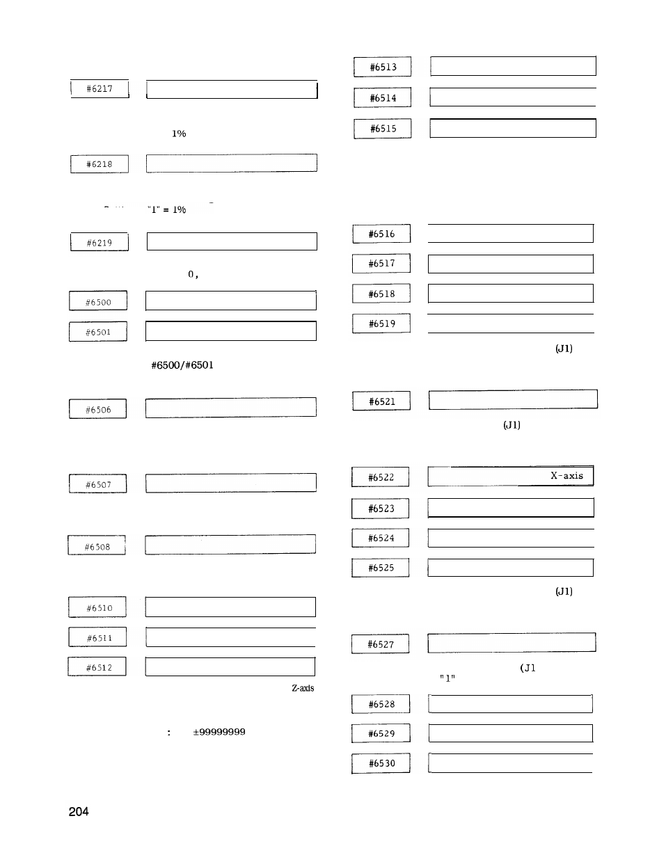
SETTING NUMBERS AND THEIR CONTENTS (Cent’d)
1
Automatic corner override F2
(n% of command feeding)
Setting : “l” =
Automatic corner override F3
(n% of command feeding)
Setting :
System
Setting
No. switch setting
range:
1, 4
Scaling multiple setting
Multiple =
Setting : “O’ = Scale multiple = 1
Angle setting during execution of commands
G76 and G77
Setting : “l” = 0.001 deg
Tool length measuring bias setting
Setting : “ 1” = Least input increment
Tool length measuring bottom level setting
Setting :
“ 1” = Least input increment
X-axis
Y-axis
1
Z-axis
Sets stored stroke limit of the X-, Y- and
and the boundary value in the positive
direction of the 2nd prohibited area.
Setting :
“ 1“ = 1 pulse
Setting range 0 to
X - a x i s
Y - a x i s
1
Z-axis
Sets stored stroke limit of the X-, Y- and Z-axis
in successive order and also the negative
direction boundary value of the 2nd prohibited
area.
Setting : “ 1“ = 1 pulse
Setting range : 0 to *99999999
I
X - a x i s
Y - a x i s
Z - a x i s
I
4th axis
I
Work coordinate system setting G54
Setting :
“ 1“ = Least input increment
Setting range : 0 to *99999999
Rotary angle setting G54
Setting : “ 1“ = 0.001 deg
* Setting is valid in C specification.
Y-axis
Z-axis
1
4th axis
Work coordinate system setting G55
Setting : “ 1” = Least input increment
Setting range : 0 to *99999999
Rotary angle setting G55
)
Setting:
= 0.001 deg
X-axis
Y-axis
Z-axis
I