Yaskawa J50M Instructions User Manual
Page 200
6.4 PREPARATION FOR STORED LEADSCREW
ERROR COMPENSATION AND STORED STROKE
Return to Reference Point
With an NC equipped with the stored
error compensation or the stored stroke limit func-
tions, either of the following two reference point
return motions must be performed after switching
on the power supply and before starting automatic
operation.
a.
b .
Manual return to reference point (See 5.2.1)
E x e c u t e G 9 1
XO YO ZO ; in the MDI
mode.
This procedure is to teach the reference point
to the control, since doing so is necessary be-
cause both pitch error compensation and stored
stroke check are performed with reference to
the reference point.
Checking Parameter
When the control is equipped with the pitch error
compensation function or the stored stroke limit
function, set this parameter to “l”. With the
p a r a m e t e r
set to “l”, a return to the
reference point is required before starting cycles,
alarm codes (001 to 004 “reference point return
2
incomplete”) are displayed, if the CYCLE
key is
pushed without making a reference point return
immediately after turning on the power supply. Be
sure to perform the operation for return to reference
point.
Set this parameter to
“ 1“ when pitch error
compensation or stored stroke limit is provided.
6.5 PREPARATION FOR AUTOMATIC
OPERATION
The machine must be positioned properly accord-
ing to the part program prior to the start of auto-
matic operation.
After positioning the absolute
coordinate system for the machining must be set
properly by manual operation or programming.
3.
1. When G92 is not programmed in a tape or
memory.
. Return the machine manually to the reference
point.
(Refer to 5.2.1.1 MANUAL RETURN TO REFERENCE
POINT).
. The G92 command according to the part pro-
gram should be executed by MDI .
G92
. Y.. .
;
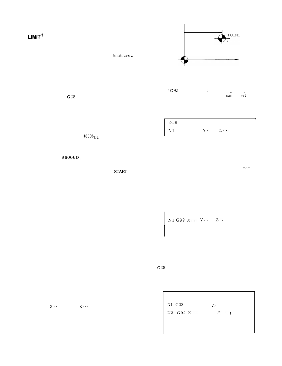
x
REFERENCE
Y
+x
ABSOLUTE ZERO POINT (O, O)
Fig.
6.1
If
XO YO ZO
s e t t i n g i s r e q u i r e d ,
the coordinate of each axis
be
to
“O” easily using ORG key.
Refer to
4. 1.9
ORG
KEY.
E X A M P L E
;
GOO X...
.
;
I
When
ory.
When
Fig. 6.2
G92 is programmed in a tape or
-
the program requires G92 to be executed at
the reference point, return the machine to the
reference point by manual return to reference point
return.
EXAMPLE :
EOR ;
.
. ;
Fig. 6.3
When G28 and G92 are programmed .
When the program begins with G28 and with
and G92, move the machine manually in-
to the area where return to reference point
can
be performed.
EXAMPLE :
EOR ;
x... y.. .
. . .,
Y.. .
192
Fig. 6.4