Yaskawa J50M Instructions User Manual
Page 193
The WSKAN1, WSH signals selected before
selecting the manual mode are invalid.
It enters the manual skip mode (
LED blinks)
only when the WSKAN1 and WSH signals are selected
after selecting the manual mode. The PST signal is also
valid only when activated (turned on from
under the
writing mode.
(d) Be sure to touch (SKIP signal ON) the datum plane
with the same axis.
(e) When the tactile sensor turns on, it must be
pulled back for a certain amount (parameter #6578) ,
or it cannot be moved in the same direction again.
TACTILE SENSOR
ON
PARAMETER #6578 1 = 1 PULSE
(f)
Tactile sensor contact signal
The tactile sensor contact signal operates in the
following timing, when the tactile sensor signal
turns on.
TACTILE
SENSOR
SIGNAL #13093
TACTILE SENSOR
I
CONTACT SIGNAL #6191
AFTER THE POSITION
—
IS FIXED
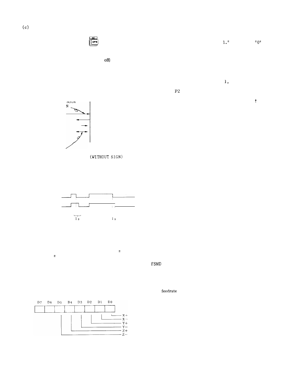
When the tactile sensor signal turns on, the tactile
sensor contact signal turns on after the position is
fixed, and when the tactile sensor signal turns off,
the tactile sensor contact signal turns off after 1
second.
The tactile sensor contact signal (#6191) is 0“
when off, and 1’ when on.
(g) Tactile sensor contact direction monitor
When the tactile sensor contact signal (see above)
turns ON, it can be made determined which axis
contacted the sensor and from which direction.
Tactile sensor contact direction monitor (#6196)
(h) Manual skip warning monitor
The following warnings appear when a measurement
mistake is made while using manual skip.
If this
warning appears, #6192 becomes “
It becomes
by resetting the warning.
(EXAMPLE)
SET P3 (Point ERROR)
(i) Manual skip measurement point monitor
Refer to parameter #6194 to find on which point the
measurement is made.
The value changes as; O, 1, 2, 0,
2.
It returns to the initial state if reset during the
setting (SET
or SET P3).
5.2.7
FEEDRATE, SPINDLE SPEED EDITING FUNCTION
(1)
O u t l i n e
The execution values of the feedrate and spindle
speed during automatic operation are stored and
feed back to the NC part program to create the
optimized program.
The feedrate (F code) and spindle speed (S code)
will be called FS in the following description.
(2)
(a)
( i )
(ii)
1/0
Input
FSCM (#13134)
FS editing
mode
Close this signal during FS editing, to prepare
for FS storage and FS memory change.
FSMEM (#13135)
FS storage
Close this signal during automatic operation to
store the operation feedrate and spindle
revolution data into the internal memory.
(iii) FSCH (#13136)
FS memory change
Close this signal while the automatic operation
is held, to reflect the data stored during
automatic operation in the NC part program.
(iv) FSCLR (#13357)
( b )
( i )
(ii)
FS
data clear
Close this signal to clear all the stored FS
data.
output
(#12090)
During FS editing mode
This signal indicates that the FSCM is closed
and it is ready for FS storage and FS memory
editing.
When this signal changes from closed-to open,
the
and spindle speed data are
canceled.
FSCE (#12091)
End of FS memory change
This signal closes when the FSCH closes and
the data are reflected in the NC part program.
It opens again when the SFCH opens again.
185