Yaskawa MP2000 Series: Built-in SVB or SVB-01 Motion Module User Manual
Page 145
4.4 MP2000 Series Machine Controller Parameter Details
4.4.3 Motion Monitoring Parameter Details
4-69
Motion Parameters
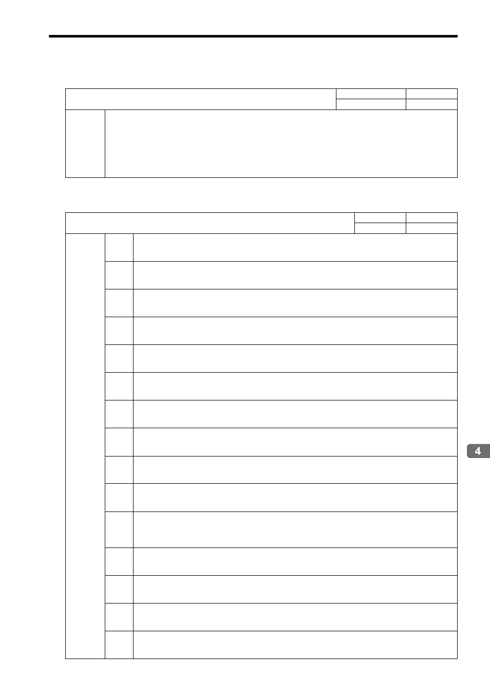
( 13 ) Servo Driver Information
( 14 ) Servo Driver I/O Monitor
Stores I/O information of the SERVOPACK.
IW
2D
Servo Driver Alarm Code
Range
Unit
−32768 to 32767
−
Description
Stores the alarm code (leftmost 2 digits) from the SERVOPACK in BCD
Example: The code for a communication error that occurs in an SGDS or SGDV SERVOPACK is E6.
Refer to the manual for the SERVOPACK for details on alarms.
When the motion command ALM_MON (Monitor SERVOPACK Alarms) or ALM_HIST (Monitor SER-
VOPACK History) is executed, the monitored alarm code will be written as it is. (3 digits for SGDS or
SGDV SERVOPACK).
When in Simulation Mode, the alarm code will be H99.
IW
2E
Servo Driver I/O Monitor
Range
Unit
−
−
Description
Bit 0
Forward Side Limit Switch Input (P_OT)
0: OFF
1: ON
Bit 1
Negative Reverse Side Limit Switch Input (N_OT)
0: OFF
1: ON
Bit 2
Deceleration Dog Switch Input (DEC)
0: OFF
1: ON
Bit 3
Encoder Phase-A Signal Input (PA)
0: OFF
1: ON
Bit 4
Encoder Phase-B Signal Input (PB)
0: OFF
1: ON
Bit 5
Encoder Phase-C Signal Input (PC)
0: OFF
1: ON
Bit 6
EXT 1 Signal Input
0: OFF
1: ON
Bit 7
EXT 2 Signal Input
0: OFF
1: ON
Bit 8
EXT 3 Signal Input (EXT3)
0: OFF
1: ON
Bit 9
Brake State Output (BRK)
0: OFF
1: ON
Bit A
Stop Signal (HWBB)
Available only for SGDV SERVOPACKs except SGDV-
E1
SERVOPACKs
0: OFF
1: ON
Bit C
CN1 Input Signal (IO12) selected in parameter Pn81E.0
0: OFF
1: ON
Bit D
CN1 Input Signal (IO13) selected in parameter Pn81E.1
0: OFF
1: ON
Bit E
CN1 Input Signal (IO14) selected in parameter Pn81E.2
0: OFF
1: ON
Bit F
CN1 Input Signal (IO15) selected in parameter Pn81E.3
0: OFF
1: ON