B ] zero method (ow 3c = 1) – Yaskawa MP2000 Series: Built-in SVB or SVB-01 Motion Module User Manual
Page 183
6.2 Motion Command Details
6.2.3 Zero Point Return (ZRET)
6-22
[ b ] ZERO Method (OW
3C = 1)
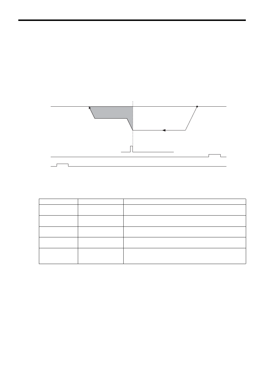
Operation after Zero Point Return Starts
Travel is started at the approach speed in the direction specified in the parameters.
When the rising edge of the ZERO signal is detected, the speed is reduced to the creep speed and positioning is per-
formed.
When the positioning has been completed, a machine coordinate system is established with the final position as the
zero point.
The moving amount after the ZERO signal is detected is set in the Zero Point Return Travel Distance (OL
42).
If an OT signal is detected during the zero point return operation, an OT alarm will occur.
* 1. The SERVOPACK EXT1 signal.
* 2. The SERVOPACK P-OT signal.
* 3. The SERVOPACK N-OT signal.
Setting Parameters
Parameter
Name
Setting
OW
3C
Zero Point Return
Method
1: ZERO Signal Method
OW
09, Bit 3
Zero Point Return Direc-
tion Selection
Set the zero point return direction.
OL
3E
Approach Speed
Set the speed to use when starting a zero point return.
Only a positive value can be set; a negative value will result in an error.
OL
40
Creep Rate
Set the speed to use after detecting the ZERO signal.
Only a positive value can be set; a negative value will result in an error.
OL
42
Zero Point Return Travel
Distance
Set the travel distance from the point where the ZERO signal is detected.
If the sign is positive, travel will be toward the zero point return direction; if
the sign is negative, travel will be away from the zero point return direction.
N-OT
∗3
P-OT
∗2
Start
Zero Point
ZERO signal
∗1
Zero Point Return Travel Distance
(OL
42)
Creep Rate
(OL
40)
Approach Speed
(OL
3E)