Yaskawa MP2000 Series: Built-in SVB or SVB-01 Motion Module User Manual
Page 405
10.4 Motion Parameter Details
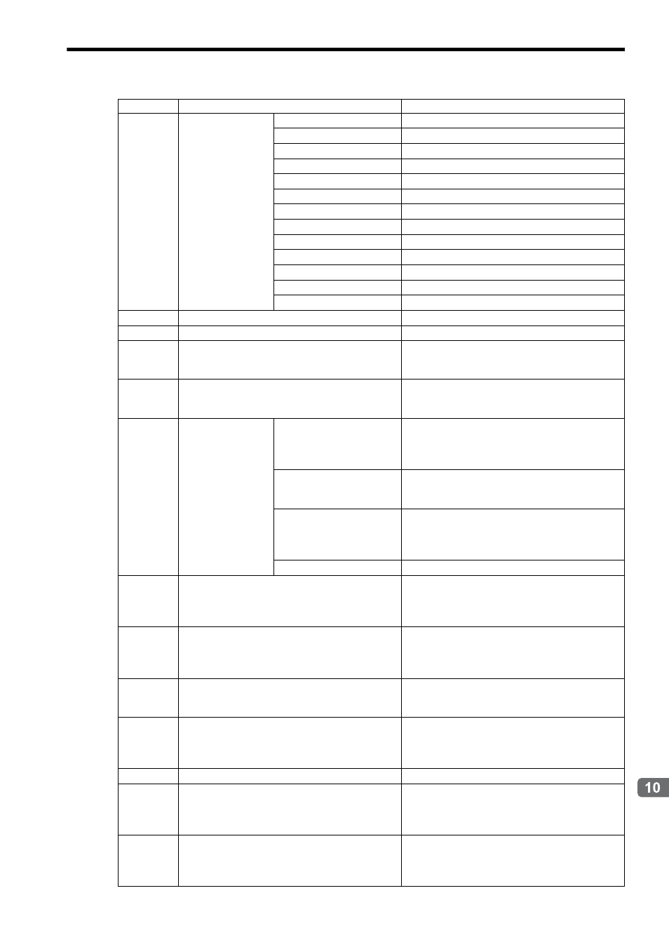
10.4.3 Monitoring Parameter List
10-41
Settings for Connecting Inverters
IW
1D
Digit Input Terminal
(Option)
Bit 0: Terminal 1 Status
0: OFF, 1: ON
Bit 1: Terminal 2 Status
0: OFF, 1: ON
Bit 2: Terminal 3 Status
0: OFF, 1: ON
Bit 3: Terminal 4 Status
0: OFF, 1: ON
Bit 4: Terminal 5 Status
0: OFF, 1: ON
Bit 5: Terminal 6 Status
0: OFF, 1: ON
Bit 6: Terminal 7 Status
0: OFF, 1: ON
Bit 7: Terminal 8 Status
0: OFF, 1: ON
Bit 8: Terminal 9 Status
0: OFF, 1: ON
Bit 9: Terminal 10 Status
0: OFF, 1: ON
Bit A: Terminal 11 Status
0: OFF, 1: ON
Bit B: Terminal 12 Status
0: OFF, 1: ON
Bits C to F
Reserved by the system
IW
1E
Multi-function Analog Input A1 (Option)
Unit: 0.1%
IW
1F
Encoder Counter (ch2) (Option)
Unit: pulse
IW
20
to
IW
2F
−
Reserved by the system
IW
30
Response Alarm Code
Range: 0 to FFFFH
Displays the alarm code returned in the response to
the MECHATROLINK command.
IW
31
Subcommand
Response Status
Bit 0: Subcommand Alarm
0: Not used
1: Alarm
Displays the response status to the subcommand.
Turns ON when of subcommand alarm activation.
Bit 1: Subcommand Warn-
ing
0: Not used
1: Warning
Turns ON when subcommand warning activation.
Bit 2: Subcommand Ready
0: Busy
1: Ready
Turns ON when the subcommand execution is com-
pleted.
Bits 3 to F
Reserved by the system
IW
32
Inverter Alarm Code
Range: 0 to FFFFH
Displays the alarm code returned in the response to
the command Alarm Monitor or Alarm History
Monitor.
IW
33
Auxiliary Inverter Alarm Code
Range: 0 to FFFFH
Displays the alarm codes returned in the response to
the subcommand Alarm Monitor or Alarm History
Monitor.
IW
34
to
IW
3B
−
Reserved by the system
IW
3C
Inverter User Constant Number
Range: 0 to FFFFH
Displays the inverter user constant number set for the
command Read User Constant or Write User Con-
stant.
IW
3D
−
Reserved by the system
IW
3E
User Constant
Reading Data 1
Range: 0 to 65535
Displays the value read out by executing the com-
mand Read User Constant. Valid when Inverter User
Constant Number Size (OW
3D) = 1 to 4.
IW
3F
User Constant
Reading Data 2
Range: 0 to 65535
Displays the value read out by executing the com-
mand Read User Constant. Valid when Inverter User
Constant Number Size (OW
3D) = 2 to 4.
Register No.
Name
Contents