3 processing after an alarm occurs, 1 ) monitoring alarms, 2 ) clearing software limit alarms – Yaskawa MP2000 Series: Built-in SVB or SVB-01 Motion Module User Manual
Page 429
11.3 Software Limit Function
11.3.3 Processing after an Alarm Occurs
11-14
11.3.3 Processing after an Alarm Occurs
( 1 ) Monitoring Alarms
If an axis exceeds a software limit, a Positive/Negative Direction Software Limit alarm will occur. This alarm can be
monitored in the Alarm monitoring parameter (IL
04).
( 2 ) Clearing Software Limit Alarms
Clear software limit alarms using the procedure below.
1.
Set the Alarm Clear bit to 1 in the RUN Command Setting (OW
00 bit F) to clear the alarm.
The alarm (IL
04) will be cleared.
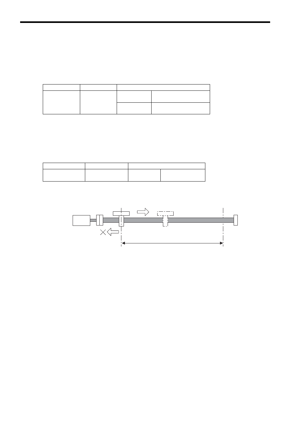
2.
Use the FEED or STEP command to return past the software limit.
Name
Register Number
Meaning
Alarm
IL
04
Bit 3:
Positive Direction Software
Limit
Bit 4:
Negative Direction Software
Limit
Name
Register Number
Meaning
RUN Command
Setting
OW
00
Bit F:
Alarm Clear
Commands will be received in the return direction.
Servo-
motor
An alarm will occur again if a command is
given in the direction of the software limit
that was activated.
Software Limit,
lower limit
Software Limit,
upper limit