Yaskawa MP2000 Series: Built-in SVB or SVB-01 Motion Module User Manual
Page 371
10.2 Operating Inverters Using an MPE720
10.2.3 Operation Procedure
10-7
Settings for Connecting Inverters
7.
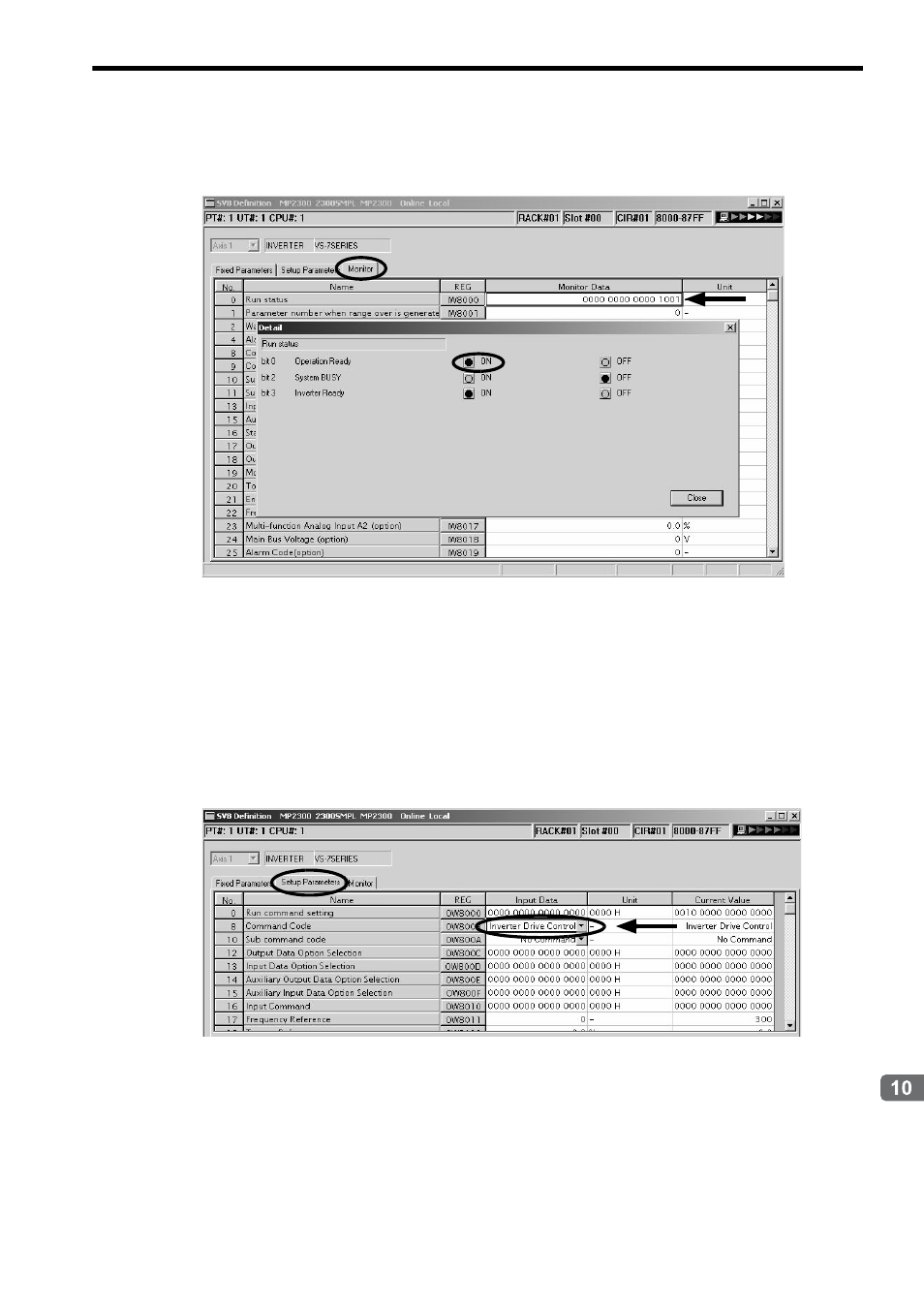
Click the Monitor Tab again to return to the Monitor Tab page, then confirm that bit 0 of the Run status
(IW
00) is set to 1 (ON).
If bit 0 is still set to 0 (OFF), return to the Setup Parameters Tab Page to see if the Command Code (OW
08)
is set to a command other than Inverter Drive Control. If it is set to Inverter Drive Control, change it to a com-
mand other than Inverter Drive Control, and set bit D (Drive Permission) of Run Command Setting parameter
(OW
00) to 0 (OFF) then to 1 (ON) again.
8.
Click the Setup Parameters Tab. Set the setting parameter Command Code (OW
08) to Inverter
Drive Control in the Setup Parameters Tab Page.
After setting bit D (Drive Permission) of Run Command Setting parameter (OW
00) in step 6, wait at least
the time equivalent to one high-speed scan to set the setting parameter Command Code.
The above settings will enable the following inverter outputs and inputs.
<Inverter Output> (Setup Parameters Tab Page)
Input Command (OW
10)
Frequency Reference (OW
11)
Torque Reference (OW
12)
<Inverter Input> (Monitor Tab Page)
Status (IW
10)
Output Frequency (IW
11)
Output Current (IW
12)