2 troubleshooting system errors, 1 outline of system errors, 1 ) system register allocations – Yaskawa MP2000 Series: Built-in SVB or SVB-01 Motion Module User Manual
Page 449
12.2 Troubleshooting System Errors
12.2.1 Outline of System Errors
12-6
12.2 Troubleshooting System Errors
This section provides troubleshooting information for system errors.
12.2.1 Outline of System Errors
The LED indicators on the front of the Basic Module can be used to determine Machine Controller operating status and
error status. To obtain more detailed information on errors, the system (S) registers can be used. A detailed check of the
contents of system registers can be used to determine the location of the error and take the corrective measures.
Details on system registers are provided below.
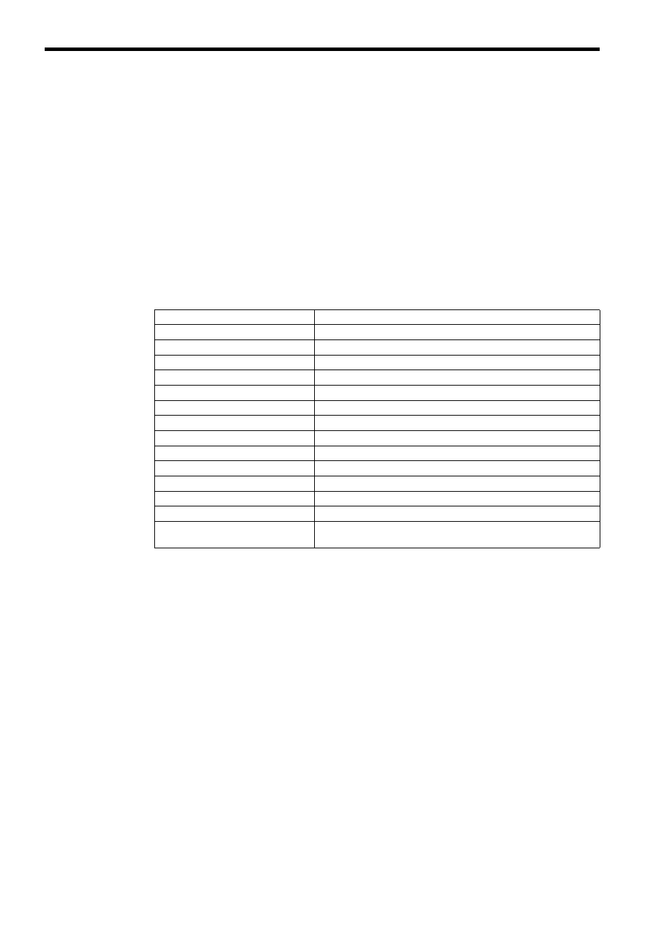
( 1 ) System Register Allocations
The following table shows the overall structure of the system registers. Refer to the sections given on the right for
details.
SW00000
System Service Register
SW00030
System Status
→
12.2.4 ( 1 ) System Status
SW00050
System Error Status
→
12.2.4 ( 2 ) System Error Status
SW00080
User Operation Error Status
→
12.2.4 ( 3 ) Ladder Program User Operation Error Status
SW00090
System Service Execution Status
→
12.2.4 ( 4 ) System Service Execution Status
SW00110
User Operation Error Status Details
→
12.2.4 ( 3 ) Ladder Program User Operation Error Status
SW00190
Alarm Counter and Alarm Clear
→
12.2.4 ( 5 ) Alarm Counter and Alarm Clear
SW00200
System I/O Error Status
→
12.2.4 ( 6 ) System I/O Error Status
SW00504
Reserved by the system
SW00698
Interrupt Status
SW00800
Module Information
→
12.2.4 ( 8 ) Module Information
SW01312
Reserved by the system
SW02048
Reserved by the system
SW03200
Motion Program Information
→
12.3 Motion Program Alarms
SW05200
to SW08191
Reserved by the system