3 servopack internal block diagrams, 1 single-phase 200 v, 50 w to 400 w models, 3 servopack internal block diagrams -7 – Yaskawa SGDH Linear Sigma Series User Manual
Page 105: 1 single-phase 200 v, 50 w to 400 w models -7
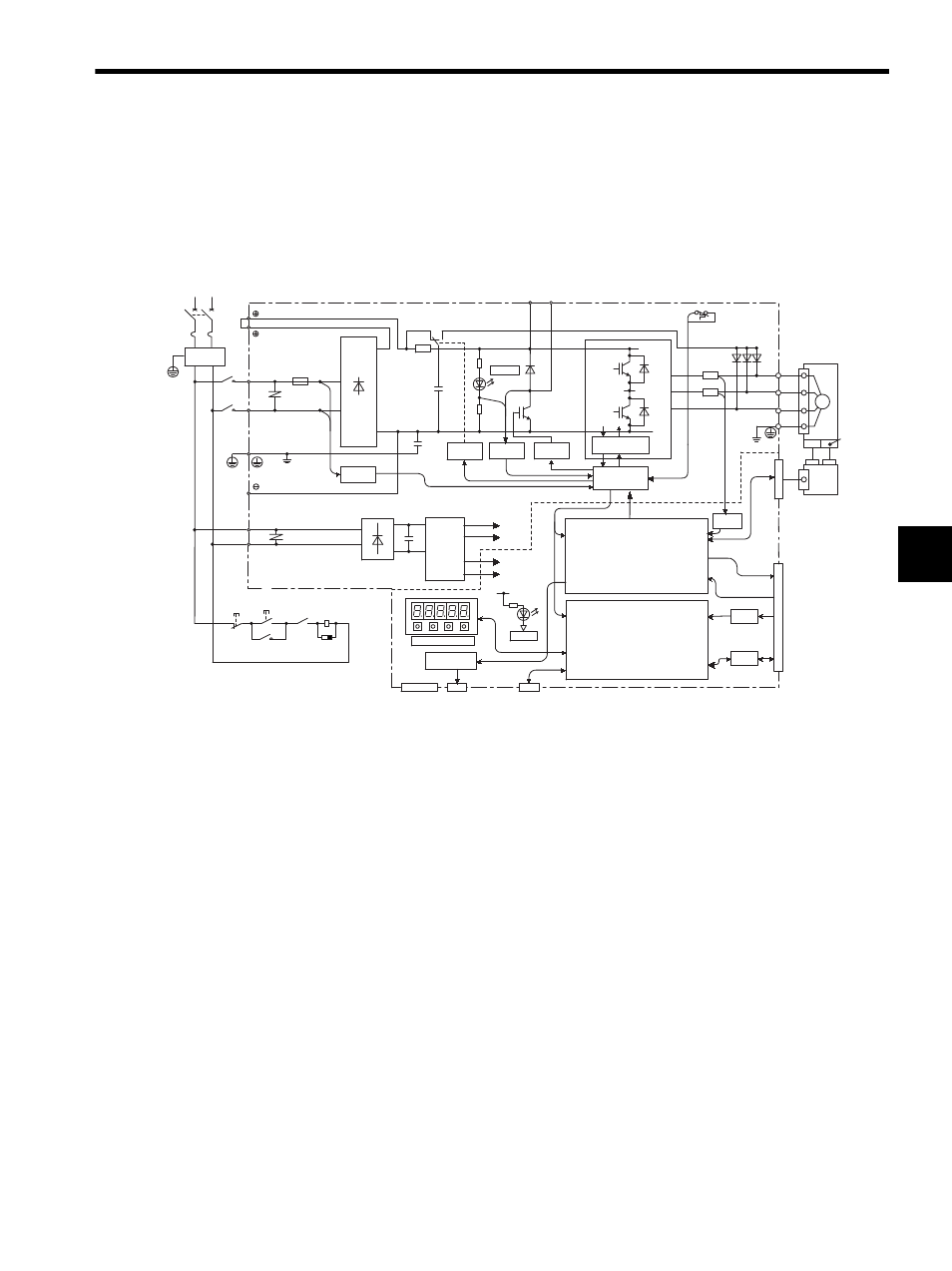
4.3 SERVOPACK Internal Block Diagrams
4-7
4
4.3 SERVOPACK Internal Block Diagrams
The following diagrams show the SERVOPACK internal blocks.
4.3.1 Single-phase 200 V, 50 W to 400 W Models
CHARGE
POWER
A/D
I/O
1KM
L1
L2
XX1
FU1
L1C
L2C
1KM
~
~
+
-
R
T
N1
TR1
C1
+5 V
0 V
CN5
CN3
+15 V
B1
B2
P2
N2
U
V
W
CN1
CN2
D2 D3 D4
THS1
R7
R8
±5 V
+5 V
±12 V
1
PM1-1
D1
RY1
PM1-2
2
+
-
+
-
U
V
W
CN10
1KM
1RY
Single-phase
200 to 230V
(50/60 Hz)
+10%
-15%
Noise
filter
Voltage
sensor
Gate drive
Relay drive
Voltage
sensor
Gate drive over-
current protector
Interface
DC/DC
converter
Analog voltage
converter
Panel operator
ASIC
CPU
(PWM control, etc.)
(Position/Speed calculation, etc.)
Power
supply
OFF
Power
supply
ON
Surge
suppressor
Open during
servo alarm (1RY)
Analog monitor
output for
supervision
Digital operator or
personal computer
Connector for
application
module
Current
sensor
PG output
Reference pulse input
Speed and Force
reference input
Sequence I/O
Linear servomotor
Hall
sensor
PG
Serial
converter
unit
M