Yaskawa SGDH Linear Sigma Series User Manual
Page 84
3 Specifications and Dimensional Drawings
3.8.1 SGLT-20 Linear Servomotors
3-36
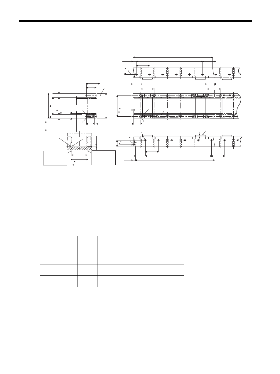
(2) Magnetic Way: SGLTM-20A
Note: 1. Two magnetic ways for both ends of coil assembly make one set. Spacers are mounted on magnetic ways
for safety during transportation. Do not remove the spacers until the coil assembly is mounted on a
machine.
2. The magnetic way may affect pacemakers. Keep a minimum distance of 200 mm from the magnetic way.
3. Two magnetic ways in a set can be connected to each other.
4. The dimensions marked with an are the dimensions between the magnetic ways. Be sure to follow
exactly the dimensions specified in the figure above. Mount magnetic ways as shown in Assembly
Dimensions. The values with an
♣ are the dimensions at preshipment.
5. Use socket headed screws of strength class 10.9 minimum for magnetic way mounting screws. Do not use
stainless steel screws.
Magnetic Way
Model SGLTM-
L1
-0.1
-0.3
L2
N
Approx.
Mass
kg (lb)
20324A
324
(12.76)
270 (10.63)
(54 (2.13)
× 5 (0.20))
6
(0.24)
3.4
(7.50)
20540A
540
(21.26)
486 (19.13)
(54 (2.13)
× 9 (0.35))
10
(0.39)
5.7
(12.57)
20756A
756
(29.76)
702 (27.64)
(54 (2.13)
× 13 (0.51))
14
(0.55)
7.9
(17.42)
Coil
assembly
Nameplate
S/N
O/N
TYPE:
MADE IN JAPAN
DATE
YASKAWA
Mount the magnetic
way so that its
corner surfaces are
flush with the inner
step.
Assembly Dimensions
C1
C1
Spacers: Do not remove until the coil
assembly is mounted on a machine.
L2
9.9
°
L2
R6
40.3
-0.2
0
L2
L1
-0.3
-0.1
L1
-0.3
-0.1
31.7
-0.2
13.7
-0.2
0
0
9.9
62
0
+0.6
R0.5 max
R1 max.
Mount the magnetic
way so that its
corner surfaces are
flush with the inner
step.
103 ( 4.06) max (preshipment)
70
±
0.3
( 2.76
±
0.001
)
15 (0.59)
15 (0.59)
19 (0.75)
Gap1
±
0.3
(0.04
±
0.01
)
32
(1.26)
8
(0.31)*
3 (0.12)
70±
0.3
( 2.76
±
0.01
)
(2.44 )
+0.02
0
55 (2.17)*
40 (1.57)
100 (3.94)
1
(0.04)
(0.54 )
-0.01
0
54 (2.13)
27 (1.06)
(1.25 )
-0.01
0
54 (2.13)
2.4±
0.3
(
0.09±
0.01
)
29.3 (1.15)*
2
×N-φ7 (φ0.28) mounting holes (See the sectional view for the depth.)
2
×N-M6 screws, depth 8 (0.31)
27 (1.06)
2.4±
0.3
(
0.09±
0.01
)
9.4
(0.37)*
(1.59 )
-0.01
0
54 (2.13)
54
(2.13)*
29.3 (1.15)*
54 (2.13)*
8 (0.31)
54
(2.13)*
* Reference length
Units: mm (in)
87 (3.43)
71.5
±
1
( 2.81
±
0.04
)
(preshipment)