Yaskawa SGDH Linear Sigma Series User Manual
Page 362
11 Inspection, Maintenance, and Troubleshooting
11.1.5 Troubleshooting of Alarm and Warning
11-10
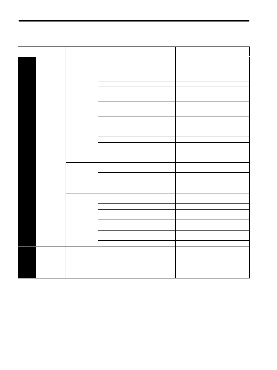
A.41
Undervoltage
(Detected when
the SERVO-
PACK’s main cir-
cuit DC voltage is
170 V or less.)
(Detected when
the power to the
main circuit is
turned ON.)
Occurred when the
control power sup-
ply was turned ON.
A SERVOPACK board fault occurred.
Replace the SERVOPACK.
Occurred when the
main circuit power
supply was turned
ON.
The AC power supply voltage is low.
The AC power supply voltage must be within the
specified range.
The fuse of the SERVOPACK is blown out.
Replace the SERVOPACK.
The surge current limit resistor is disconnected,
resulting in an abnormal power supply voltage or in
an overload of the surge current limit resistor.
Replace the SERVOPACK. Check the power sup-
ply voltage, and reduce the number of times that
the main circuit is turned ON or OFF.)
A SERVOPACK fault occurred.
Replace the SERVOPACK.
Occurred during
normal operation.
The AC power supply voltage was lowered, and
large voltage drop occurred.
The AC power supply voltage must be within the
specified range.
A temporary power failure occurred.
Clear and reset the alarm, and restart the opera-
tion.
The servomotor main circuit cable is short-circuited.
Repair or replace the servomotor main circuit
cable.
The servomotor is short-circuited.
Replace the servomotor.
A SERVOPACK fault occurred.
Replace the SERVOPACK.
A.51
Overspeed
(Detected when
the feedback
speed is the maxi-
mum motor
speed)
Occurred when the
control power sup-
ply was turned ON.
A SERVOPACK board fault occurred.
Replace the SERVOPACK.
Occurred when
servo was ON.
The order of phases U, V, and W in the servomotor
wiring is incorrect.
Correct the servomotor wiring.
The encoder wiring is incorrect.
Correct the encoder wiring.
Malfunction occurred due to noise interference in
the encoder wiring.
Take measures against noise for the encoder wir-
ing.
A SERVOPACK fault occurred.
Replace the SERVOPACK.
Occurred when the
servomotor started
running or in a
high-speed move-
ment.
The order of phases U, V, and W in the servomotor
wiring is incorrect.
Correct the servomotor wiring.
The encoder wiring is incorrect.
Correct the encoder wiring.
Malfunction occurred due to noise interference in
the encoder wiring.
Take measures against noise for the encoder wir-
ing.
The position or speed reference input is too large.
Reduce the reference value.
The setting of the reference input gain is incorrect.
Correct the reference input gain setting.
The divided output frequency exceeds 15 MHz.
Correct the setting for dividing output.
Decrease the maximum speed.
A SERVOPACK board fault occurred.
Replace the SERVOPACK.
A.55
Linear Servomo-
tor Maximum
Speed Setting
Error
(For the software
version 32 or
later)
Occurred when the
control power sup-
ply was turned ON.
When connecting the linear servomotor, a value
higher than the linear servomotor peak speed was set
for Pn384.
Check the maximum speed of the allowable linear
servomotor with Un010 and then set Pn384 to a
value that is lower than the maximum speed of the
linear servomotor.
Table 11.5 Alarm Display and Troubleshooting (Cont’d)
Alarm
Display
Alarm Name
Situation at Alarm
Occurrence
Cause
Corrective Actions