2 position control mode, 2 position control mode -24 – Yaskawa SGDH Linear Sigma Series User Manual
Page 188
7 Wiring
7.4.2 Position Control Mode
7-24
7.4.2 Position Control Mode
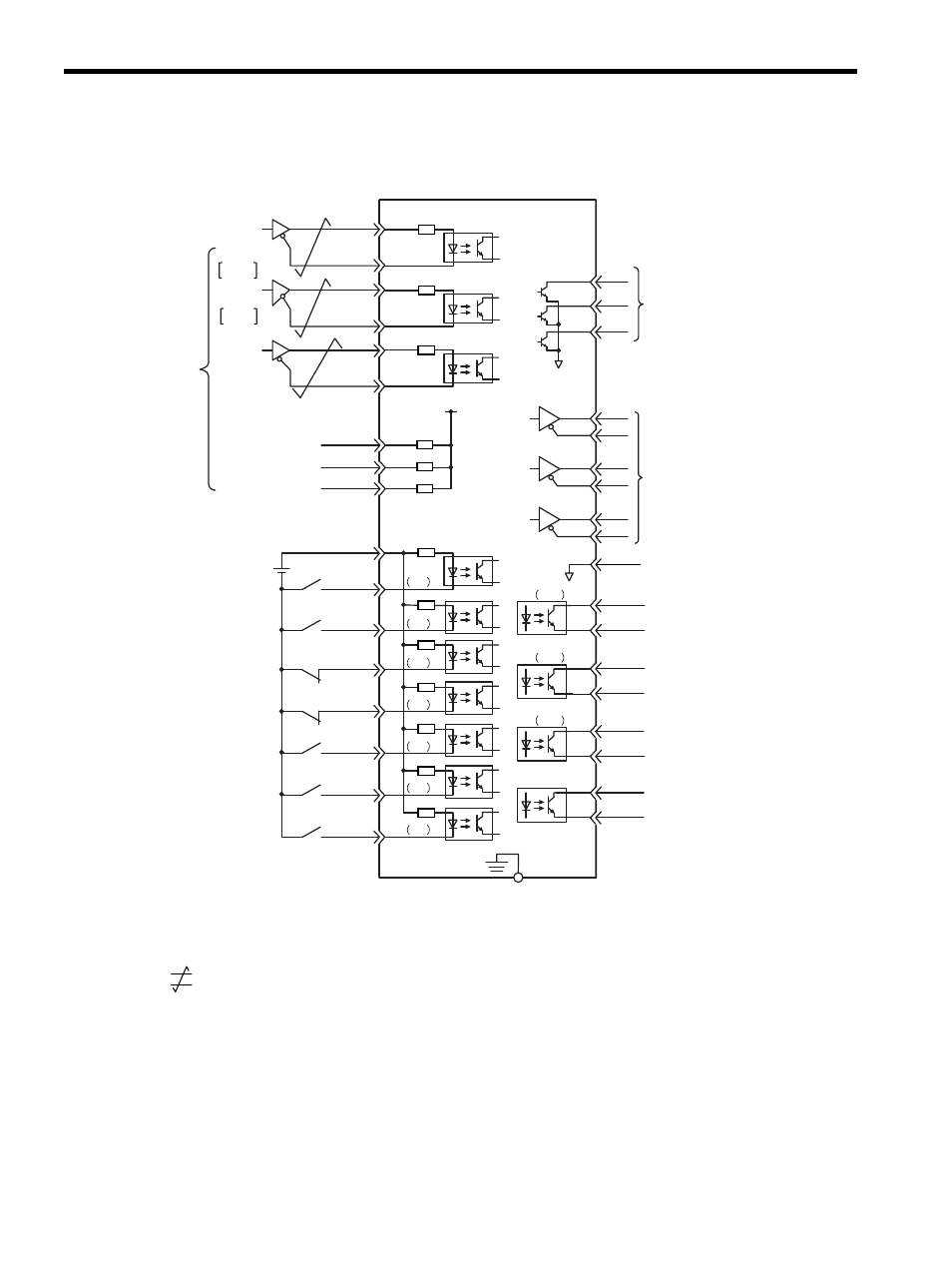
* 1.
: represents twisted-pair wires.
* 2. Customers must purchase a 24 VDC power supply with double-shielded enclosure.
Note: The functions allocated to the input signals SI0 to SI6 and the output signals SO1 to SO3 can be
changed by using the parameters. Refer to 8.3.2 Input Circuit Signal Allocation and 8.3.3 Output
Circuit Signal Allocation.
ALO1
ALO2
ALO3
PBO
PCO
/PBO
PAO
/PAO
/PCO
/COIN+
/COIN-
/TGON+
/TGON-
/S-RDY+
ALM+
ALM-
FG
14
15
27
28
29
30
31
32
SO1
SI0
SI1
SI2
SI3
SI4
SI5
SI6
SO2
SO3
26
25
19
33
34
35
36
20
37
38
39
+24V
+24VIN
3.3k
Ω
/S-ON
/P-CON
P-OT
N-OT
/ALM-RST
/N-CL
47
41
43
42
44
45
/P-CL
46
40
/S-RDY-
Alarm code output
Max. operating voltage:
30 VDC
Max. output current:
20 mA DC
PG dividing ratio output
Applicable line receiver:
SN75175 manufactured
by Texas Instruments or
the equivalent
corresponding to
MS3486
Servo ON
(Servo ON when ON)
Reverse run prohibited
(Prohibited when OFF)
Forward run prohibited
(Prohibited when OFF)
Alarm reset
(Reset when ON)
Reverse current limit
(Limited when ON)
Forward current limit
(Limited when ON)
Connect the shielded wire
to the connector shell.
Connector
shell
∗2.
P control
(P control when ON)
Positioning completed
(ON when positioning
completes)
Movement speed
detection output
(ON above the setting)
Servo ready output
(ON when ready)
Servo alarm output
(OFF for an alarm)
Photocoupler output
Max. operating voltage:
30 VDC
Max. output current:
50 mA DC
150
Ω
PULS
SIGN
CLR
/PULS
SIGN
/SIGN
CLR
/CLR
PULS
SERVOPACK
Position
reference
CW
Phase A
CCW
Phase B
∗1.
1
SG
PL1
PL2
PL3
+12 V
Open-collector
reference
power supply
1k
Ω
3
13
18
7
8
12
11
150
Ω
150
Ω