Yaskawa SGDH Linear Sigma Series User Manual
Page 414
12 Appendix
12.4.2 List of Parameters
12-38
* Available for the software version 32 or later
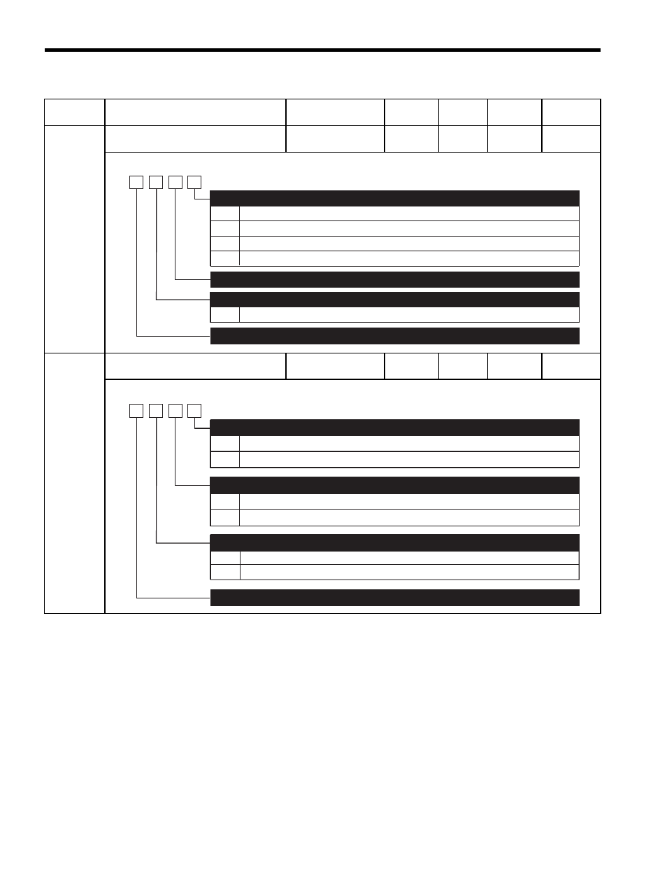
Pn510
Output Signal Selection 3
−
−
0000
After
restart
Pn512
Output Signal Reverse Settings
−
−
0000
After
restart
Parameter
No.
Name
Setting Range
Unit
Factory
Setting
Setting
Validation
Reference
Section
0
1
2
3
Disabled (the above signal is not used.)
Outputs the signal from CN1-25, -26 terminal.
Outputs the signal from CN1-27, -28 terminal.
Outputs the signal from CN1-29, -30 terminal.
Near Signal Mapping (/NEAR)
0 to 3 Same as /NEAR
Reference Pulse Input Switch Signal Mapping (/P-SELA)
∗
4th
digit
3rd
digit
2nd
digit
1st
digit
n.
Reserved (Do not change)
Reserved (Do not change)
0
1
0
1
0
1
Output signal is not reversed.
Output signal is reversed.
Output signal is not reversed.
Output signal is reversed.
Output signal is not reversed.
Output signal is reversed.
Output Signal Reverse for CN1-25 or -26 Terminals
4th
digit
3rd
digit
2nd
digit
1st
digit
n.
Output Signal Reverse for CN1-27 or -28 Terminals
Output Signal Reverse for CN1-29 or -30 Terminals
Reserved (Do not change)