Yaskawa SGDH Linear Sigma Series User Manual
Page 402
12 Appendix
12.4.2 List of Parameters
12-26
* 1. If the linear servomotor with a hall sensor is used, software version 32 or later can be used.
If software version earlier than 32 is used, set to zero.
* 2. Available only for the software version 32 or later.
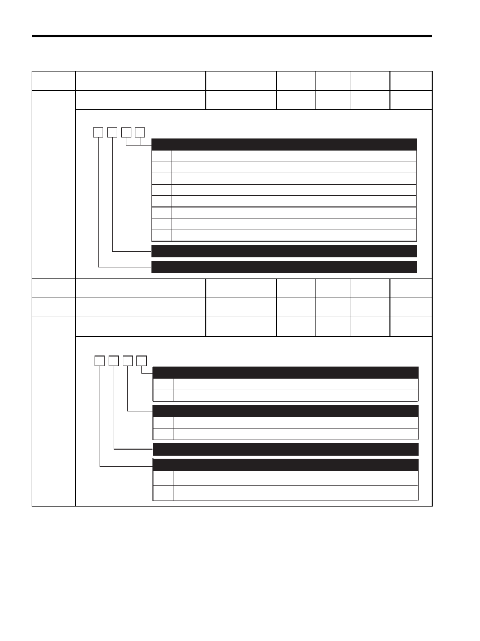
Pn003
Function Selection Application Switches 3
−
−
0002
Immedi-
ately
−
Pn004
Reserved (Do not change)
−
−
0000
Immedi-
ately
−
Pn005
Reserved (Do not change)
−
−
0000
Immedi-
ately
−
Pn080
Function Selection Application Switches
80
−
−
0000
After
restart
−
Parameter
No.
Name
Setting Range
Unit
Factory
Setting
Setting
Validation
Reference
Section
00
01
02
03
04
05
06
07
Motor speed: 1V/1000 mm/s
Speed reference: 1V/1000 mm/s
Force reference: 1V/100%
Position error: 0.05V/1 reference unit
Position error: 0.05V/100 reference units
Reference pulse frequency: 1V/1000 mm/s
Motor speed
× 4: 1V/250 mm/s
Motor speed
× 8: 1V/125 mm/s
Analog Monitor 1 / Analog Monitor 2 Signals
(Refer to 10.5 Analog Monitor.)
4th
digit
3rd
digit
2nd
digit
1st
digit
n.
Reserved (Do not change)
Reserved (Do not change)
(Refer to 10.5 Analog Monitor.)
0
1
0
1
With hall sensor
Without hall sensor
Phase A progression in order of phase U, V, and W
Phase B progression in order of phase U, V, and W
Hall Sensor Selection
(Refer to 9.2.3 )
Motor Phase Order Selection
∗1
(Refer to 9.2.2, 9.2.3)
0
1
Calculates the encoder output resolution max. value by fixing the motor max.
speed and the monitor displays Un010.
Calculation of Motor Max. Speed and Encoder Output Resolution Max. Value Selection
∗2
4th
digit
3rd
digit
2nd
digit
1st
digit
n.
Reserved (Do not change)
Calculates the motor max. speed by fixing the encoder output resolution max.
value and the monitor displays Un010.