12 control mode selection, 1 setting parameters, 2 switching the control mode – Yaskawa SGDH Linear Sigma Series User Manual
Page 318: 12 control mode selection -74
9 Operation
9.12.1 Setting Parameters
9-74
9.12 Control Mode Selection
The methods and conditions for switching SERVOPACK control modes are described below.
9.12.1 Setting Parameters
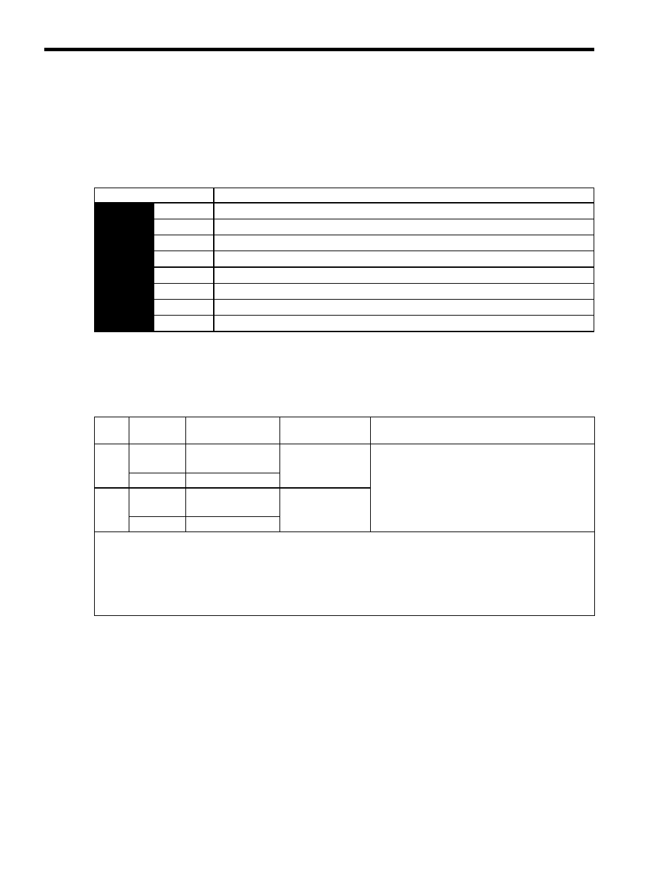
The following combinations of control modes can be selected according to the application at hand.
9.12.2 Switching the Control Mode
(1) Switching Internally Set Speed Control (Pn000.1 = 4, 5, or 6)
With the sequence input signals in the factory setting (Pn50A = n.0), the control mode will switch when
both /P-CL (/SPD-A) and /N-CL (/SPD-B) signals are OFF (high level).
Parameter
Control Method
Pn000
n.4
Internally set speed control (contact reference)
⇔
Speed control (analog voltage reference)
n.5
Internally set speed control (contact reference)
⇔
Position control (pulse train reference)
n.6
Internally set speed control (contact reference)
⇔
Force control (analog voltage reference)
n.7
Position control (pulse train reference)
⇔
Speed control (analog voltage reference)
n.8
Position control (pulse train reference)
⇔
Force control (analog voltage reference)
n.9
Force control (analog voltage reference)
⇔
Speed control (analog voltage reference)
n.A
Speed control (analog voltage reference)
⇔
Zero clamp
n.B
Position control (pulse train reference)
⇔
Position control (inhibit)
Type
Signal
Name
Connector
Pin Number
Setting
Meaning
Input
/P-CL
CN1-45
(Factory setting)
OFF (high level)
Switches control mode.
(/SPD-A)
Must be allocated
Input
/N-CL
CN1-46
(Factory setting)
OFF (high level)
(/SPD-B)
Must be allocated
Input Signal Selection
The following two types of control mode selection are available for switching from internally set speed control:
• Switching with the /P-CL and /N-CL input signals (pins allocated in factory setting)
• Switching with the /SPD-A and /SPD-B input signals
When using /SPD-A and /SPD-B, they must be allocated with parameter Pn50C. Refer to 8.3.2 Input Circuit Signal Alloca-
tion
.