2 wiring main circuit, 1 names and functions of main circuit terminals, 2 wiring main circuit -16 – Yaskawa SGDH Linear Sigma Series User Manual
Page 180: Caution
7 Wiring
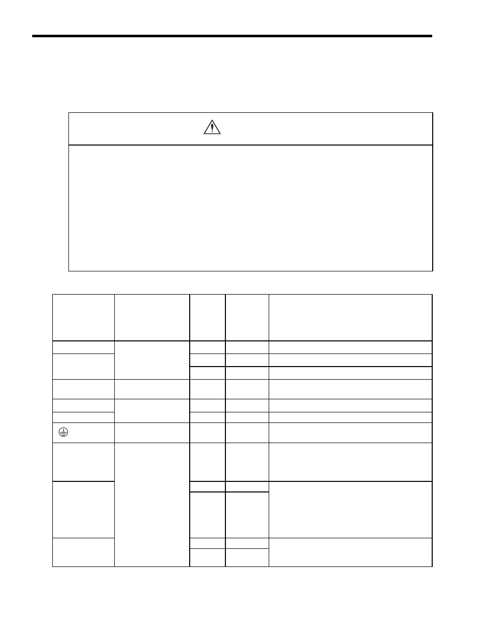
7.2.1 Names and Functions of Main Circuit Terminals
7-16
7.2 Wiring Main Circuit
This section describes typical examples of main circuit wiring, functions of main circuit terminals, and the power
ON sequence.
7.2.1 Names and Functions of Main Circuit Terminals
* If using the main circuit power supply and the control power supply with DC power supply input, refer
to 7.2.3 Typical Main Circuit Wiring Examples (4) DC Power Supply Input for more information on
wiring.
• Do not bundle or run power and signal lines together in the same duct. Keep power and signal lines sepa-
rated by at least 300 mm (11.81 in).
Failure to observe this caution may result in malfunction.
• Use twisted-pair shielded wires or multi-core twisted pair shielded wires for signal and encoder (PG) feed-
back lines.
The maximum length is 3 m (118.11 in) for reference input lines and is 20 m (787.40 in) for PG feedback lines.
• Do not touch the power terminals for five minutes after turning power OFF because high voltage may still
remain in the SERVOPACK.
Make sure the charge indicator is turned OFF first before starting an inspection.
• Avoid frequently turning power ON and OFF. Do not turn the power ON or OFF more than once per minute.
Since the SERVOPACK has a capacitor in the power supply, a high charging current flows for 0.2 seconds when the
power is turned ON. Frequently turning the power ON and OFF causes main power devices such as capacitors and
fuses to deteriorate, resulting in unexpected problems.
Terminal Symbol
Name
Main
Circuit
Voltage
(V)
Maximum
Applicable
Servomotor
Capacity
(kW)
Functions
L1, L2
Main circuit power
supply input terminal
200
0.05 to 0.4
Single-phase 200 to 230 VAC
+10%,-15%
(50/60 Hz)
∗
L1, L2, L3
200
0.5 to 7.5
Three-phase 200 to 230 VAC
+10%, -15%
(50/60 H)
∗
400
0.5 to 7.5
Three-phase 380 to 480VAC
+10%, -15%
(50/60 Hz)
∗
U, V, W
Servomotor
connection terminals
−
−
Connects to the servomotor.
L1C, L2C
Control circuit power
supply input terminal
200
0.05 to 7.5
Single-phase 200 to 230 VAC
+10%, -15%
(50/60 Hz)
∗
24V, C0V
400
0.5 to 7.5
24 VDC (
±15%)
Ground terminals
−
−
Connects to the power supply ground terminals and
servomotor ground terminal.
B1, B2
External
regenerative
resistor connection
terminal
200
0.05 to 0.4
Normally not connected.
Connect an external regenerative resistor (provided
by customer) between B1 and B2 if the regenerative
capacity is insufficient.
B1, B2, B3
200
0.5 to 5.0
Normally short B2 and B3 (for an internal regenera-
tive resistor).
Remove the wire between B2 and B3 and connect an
external regenerative resistor (provided by customer)
between B1 and B2 if the capacity of the internal
regenerative resistor is insufficient.
400
0.5 to 5.0
B1, B2
200
7.5
Connect an external regenerative resistor (provided
by customer) between B1 and B2. Refer to 7.6 Con-
necting Regenerative Resistors for details.
400
7.5
CAUTION