3 force control mode, 3 force control mode -25 – Yaskawa SGDH Linear Sigma Series User Manual
Page 189
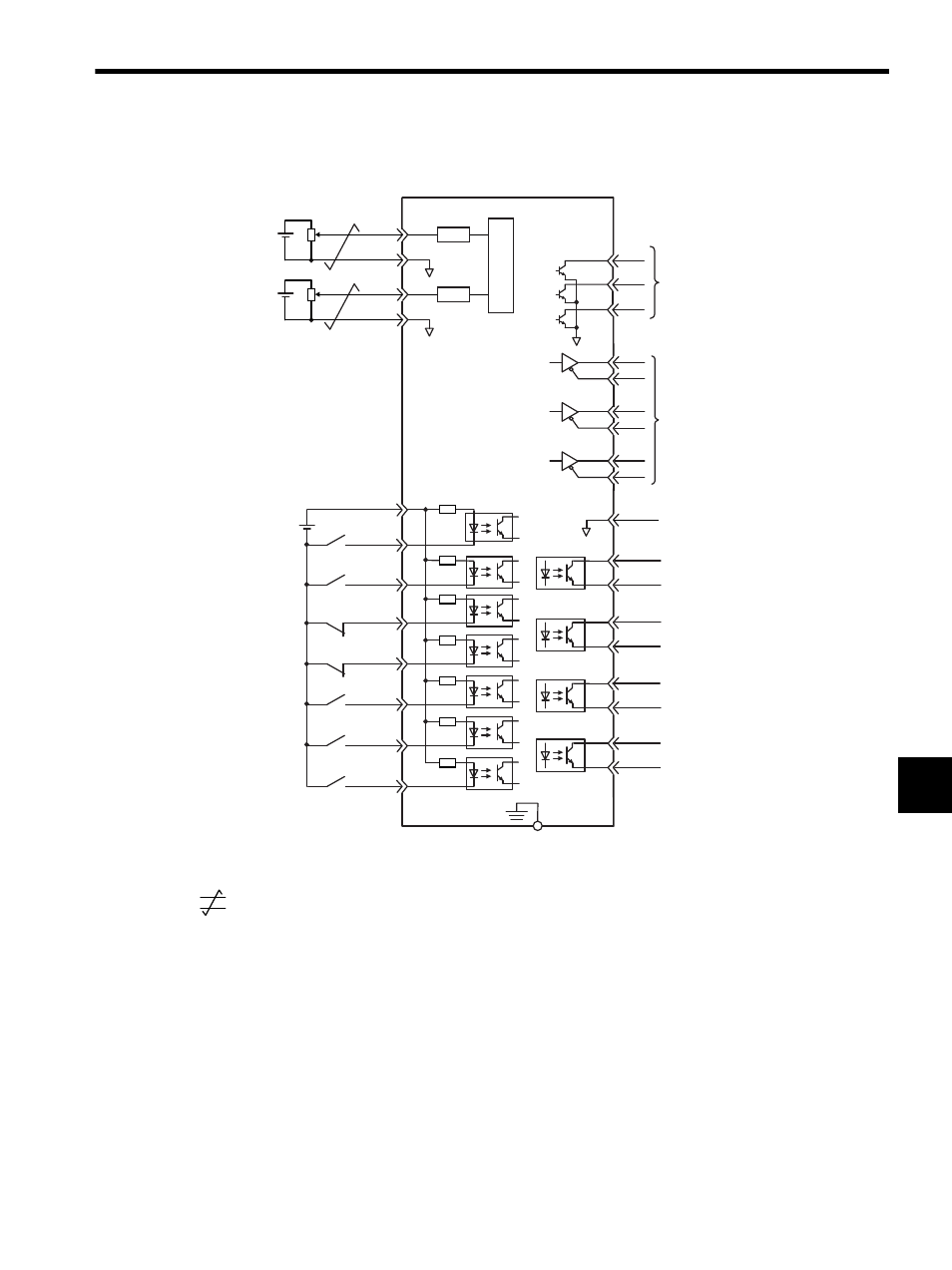
7.4 Examples of I/O Signal Connections
7-25
7
7.4.3 Force Control Mode
* 1.
: represents twisted-pair wires.
* 2. The time constant for the primary filter is 47
μs.
* 3. Enabled by the parameter setting.
* 4. Enabled by the parameter setting.
* 5. Customers must purchase a 24 VDC power supply with double-shielded enclosure.
Note: The functions allocated to the input signals SI0 to SI6 and the output signals SO1 to SO3 can be
changed by using the parameters. Refer to 8.3.2 Input Circuit Signal Allocation and 8.3.3 Output
Circuit Signal Allocation.
SERVOPACK
PBO
PCO
/PBO
PAO
/PAO
/PCO
/VLT+
/VLT-
/TGON+
/TGON-
/S-RDY+
ALM+
ALM-
FG
10
27
28
29
30
31
32
25
(SO1)
(SI0)
(SI1)
(SI2)
(SI3)
(SI4)
(SI5)
(SI6)
(SO2)
(SO3)
26
19
33
34
35
36
20
+24 V
+24VIN
3.3 k
Ω
/S-ON
/P-CON
P-OT
N-OT
/ALM-RST
/N-CL
47
41
43
42
44
45
/P-CL
46
40
/S-RDY-
V-REF
SG
A / D
5
6
∗2.
∗1.
LPF
T-REF
SG
9
∗2.
∗5.
LPF
ALO1
ALO2
ALO3
37
38
39
1
SG
Servo ON
(Servo ON when ON)
Reverse run prohibited
(Prohibited when OFF)
Forward run prohibited
(Prohibited when OFF)
Alarm reset
(Reset when ON)
Reverse current limit
(Limit when ON)
Forward current limit
(Limit when ON)
P control
(P control when ON)
Force reference
(
±
1 to
±
10 V
/rated force)
∗3 .
External speed limit
(
±
2 to
±
10 V
/rated motor speed)
PG dividing ratio output
Applicable line receiver
SN75175 manufactured
by Texas Instruments or
the equivalent corresponding
to MC3486
Connect shield to
connector shell.
Connector
shell
TGON output
(ON at levels above the setting.)
Servo alarm output
(OFF for an alarm)
Photocoupler output
Max. operating voltage:
30 VDC
Max. operating current:
50 mA DC
Speed limit output
(ON when the motor’s
running speed is limited.)
∗4.
Alarm code output
Max. operating voltage:
30 VDC
Max. operating current:
20 mA DC
Servo ready output
(ON when ready)