Yaskawa SGDH Linear Sigma Series User Manual
Page 51
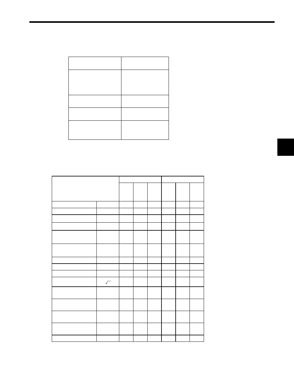
3.1 Ratings and Specifications of SGLGW/SGLGM
3-3
3
2. The above specifications show the values under the cooling condition when a heat sink (aluminium board)
listed in the following table is mounted on the coil assembly.
The values of peak speed in the table indicate the maximum speed that can be controlled from SERVOPACK. Refer to
Force and Speed Characteristics for the actual motor peak speed.
(b) With High-force Magnetic Ways
The following table shows the ratings and specifications when the high-force magnetic ways are used.
Linear Servomotor
Model SGLGW-
Heat Sink Size
in mm (in)
30A050C
30A080C
40A140C
60A140C
200
× 300 × 12
(7.87
× 11.81 × 0.47)
40A253C
60A253C
300
× 400 × 12
(11.81
× 15.75 × 0.47)
40A365C
60A365C
400
× 500 × 12
(15.75
× 19.69 × 0.47)
90A200C
90A370C
90A535C
800
× 900 × 12
(31.50
× 35.43 × 0.47)
Linear Servomotor
Model SGLGM-C-M
+
SGLGW-
40A
60A
140C 253C 365C 140C 253C 365C
Rated Speed
m / s
1.5
1.5
1.5
1.5
1.5
1.5
Peak Speed
m / s
5
5
5
5
5
5
Rated Force
∗
N
57
114
171
85
170
255
Rated Current
∗
A
rms
0.8
1.6
2.4
1.2
2.2
3.3
Instantaneous Peak
Force
∗
N
230
460
690
360
720
1080
Instantaneous Peak
Current
∗
A
rms
3.2
6.5
9.7
5.0
10.0
14.9
Coil Assembly Mass kg
0.34
0.60
0.87
0.42
0.76
1.10
Force Constant
N / A
rms
76.0
76.0
76.0
77.4
77.4
77.4
BEMF Constant
V /(m / s)
25.3
25.3
25.3
25.8
25.8
25.8
Motor Constant
9.6
13.6
16.7
12.9
18.2
22.3
Electrical Time
Constant
ms
0.4
0.4
0.4
0.5
0.5
0.5
Mechanical Time
Constant
ms
3.69
3.24
3.12
2.52
2.29
2.21
Thermal Resistance
With Heat Sink
K / W
1.67
0.87
0.58
1.56
0.77
0.51
Thermal Resistance
Without Heat Sink
K / W
3.02
1.80
1.23
2.59
1.48
1.15
Magnetic Attraction
N
0
0
0
0
0
0
N /
w