Yaskawa SGDH Linear Sigma Series User Manual
Page 369
11.1 Troubleshooting
11-17
11
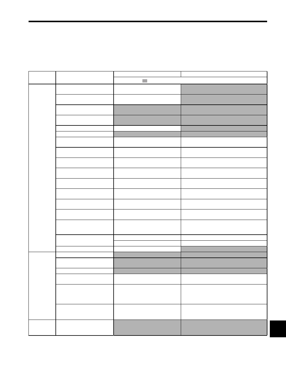
11.1.6 Troubleshooting for Malfunction without Alarm Display
The troubleshooting for the malfunctions that causes no alarm display is listed below.
Contact your Yaskawa representative if the problem cannot be solved by the described corrective actions.
Table 11.7 Troubleshooting for Malfunction without Alarm Display
Symptom
Cause
Inspection
Corrective Actions
: Turn OFF the servo system before executing operations.
Linear Servo-
motor Does
Not Start
The control power supply is not ON.
Check voltage between control power sup-
ply terminals.
Correct the control power circuit.
The main circuit power supply is not
ON.
Check the voltage between power supply
terminals.
Correct the power circuit.
Wrong wiring or disconnection of
I/O signal connector CN1
Check if the connector CN1 is properly
inserted and connected.
Correct the connector CN1 connection.
Linear servomotor or serial converter
unit wiring disconnected.
Check the wiring.
Correct the wiring.
Overloaded
Run under no load.
Reduce load or replace with larger capacity servomotor.
Speed/position references not input
Check reference input pins.
Input speed/position references correctly.
Setting for Pn50A to Pn50D “Input
Signal Selection” is incorrect.
Check settings of parameters Pn50A to
Pn50D.
Correct the settings for Pn50A to Pn50D “Input Signal
Selection.”
/S-ON input signal stays OFF.
Check settings of parameters Pn50A.0 and
Pn50A.1.
Correct the parameter setting and turn ON /S-ON input
signal.
Control method selection is incor-
rect.
Check parameter Pn000.1.
Set parameters to match the application.
Reference pulse mode selection is
incorrect.
Check the parameter setting for the refer-
ence pulse mode (Pn200.0).
Correct setting of parameter Pn200.0.
Speed control: Speed reference input
is incorrect.
Check V-REF and SG to confirm if the con-
trol method and the input are agreed.
Correct the control mode selection parameter, or the
input.
Force control: Force reference input
is incorrect.
Check T-REF and SG to confirm if the con-
trol method and the input are agreed.
Correct the control mode selection parameter, or the
input.
Position control: Reference pulse
input is incorrect.
Check Pn200.0 reference pulse form or sign
+ pulse signal.
Correct the setting of Pn200.0 or the input.
The error clear counter (CLR) input
is turned ON.
Check CLR or /CLR input pins (CN1-14
and -15).
Turn CLR or /CLR input signal OFF.
The forward run prohibited (P-OT)
or reverse run prohibited (N-OT)
input signal is turned OFF.
Check P-OT or N-OT input signal.
Turn P-OT or N-OT input signal ON.
The polarity detection is not exe-
cuted.
Check the parameter Pn080.
Correct the setting of Pn080.
Check /S-ON or /P-DET input signal.
Turn /S-ON or /P-DET input signal ON.
A SERVOPACK fault occurred.
A SERVOPACK board fault occurred.
Replace the SERVOPACK.
Linear Servo-
motor Moves
Instanta-
neously, and
then Stops
Servomotor wiring is incorrect.
Check the servomotor wiring.
Correct the servomotor wiring.
Serial converter unit wiring is incor-
rect.
Check the serial converter unit wiring.
Correct the serial converter unit wiring.
Linear scale wiring is incorrect.
Check the linear scale wiring.
Correct the linear scale wiring.
Linear scale pitch (Pn280) is incor-
rect.
Check the setting of Pn280.
Correct the setting of Pn280.
Linear scale counting up direction
and linear servomotor coil assembly
forward direction are not agreed.
Check the directions.
Change the setting of Pn080.1 (Servomotor Phase Order
Selection).
Match the linear scale direction and coil assembly direc-
tion.
Polarity detection is not performed
correctly.
Check if the value of Un004 (Electrical
Angle 2) at an arbitrary position is between
±
10 degrees.
Correct the settings for the polarity detection related
parameter.
Linear Servo-
motor Speed
Unstable
Wiring connection to servomotor is
defective.
Check connection of power lead (phases U,
V, and W) and encoder connectors.
Tighten any loose terminals or connectors.