Yaskawa SGDH Linear Sigma Series User Manual
Page 319
9.12 Control Mode Selection
9-75
9
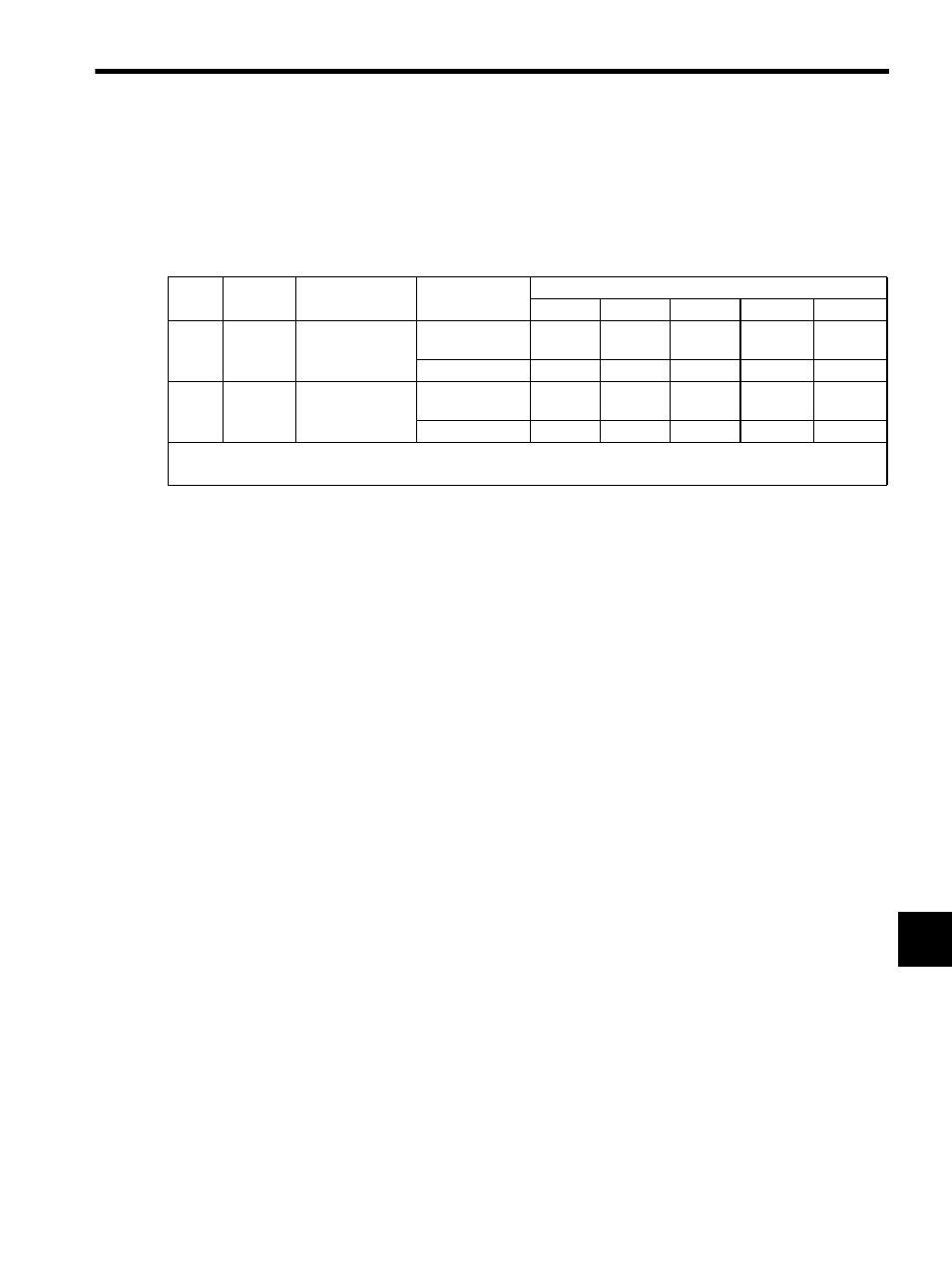
(2) Switching Other Than Internally Set Speed Control (Pn000.1 = 7, 8, 9, A, or B)
Use the following signals to switch control modes. The control modes switch as shown below for each of the sig-
nal states indicated.
When changing the sequence input signal from the factory setting (Pn50A = n.1), allocate the /C-SEL to
an input terminal and change modes with the /C-SEL signal. In this case, input a speed reference (analog voltage
reference) for speed control, and a position reference (pulse train reference) for position control.
Type
Signal
Name
Connector
Pin Number
Setting
Pn000 Setting
n.7 n.8 n.9 n.A n.B
Input
/P-CON
CN1-41
(Factory setting)
ON (low level)
Speed
Force
Speed
Zero
clamp
Inhibit
OFF (high level)
Position
Position
Force
Speed
Position
(Input) (/C-SEL)
Must be allocated
ON (low level)
Speed
Force
Speed
Zero
clamp
Inhibit
OFF (high level)
Position
Position
Force
Speed
Position
The control mode can be switched with either /P-CON or /C-SEL.
When using the /C-SEL signal, the input signal must be allocated. Refer to 8.3.2 Input Circuit Signal Allocation