5 i/o signal (cn1) names and functions, 5 i/o signal (cn1) names and functions -27, 1) input signals – Yaskawa SGDH Linear Sigma Series User Manual
Page 191
7.4 Examples of I/O Signal Connections
7-27
7
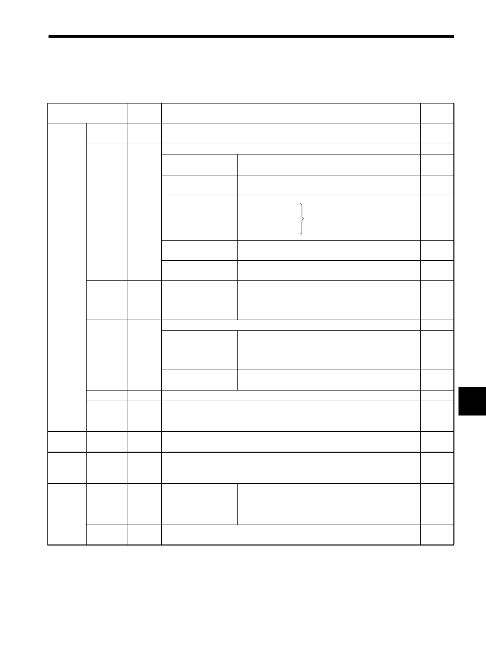
7.4.5 I/O Signal (CN1) Names and Functions
(1) Input Signals
Note: 1. Pin numbers in parentheses () indicate signal grounds.
2. The functions allocated to /S-ON, /P-CON. P-OT, N-OT, /ALM-RST, /P-CL, and /N-CL input
signals can be changed by using the parameters. Refer to 8.3.2 Input Circuit Signal Allocation.
3. The voltage input range for speed and force references is a maximum of
±12 V.
Signal Name
Pin No.
Function
Refer-
ence
Common
/S-ON
40
Servo ON: Turns ON the linear servomotor when the gate block in the inverter is
released.
/P-CON
41
Function selected by parameter.
−
Proportional control
reference
Switches the speed control loop from PI (proportional/
integral) to P (proportional) control when ON.
Direction reference
With the internal set speed selected: Switch the movement
direction.
Control mode
switching
Zero-clamp reference
Speed control with zero-clamp function: Reference
speed is zero when ON.
Reference pulse block
Position control with reference pulse stop: Stops reference
pulse input when ON.
P-OT
N-OT
42
43
Forward run
prohibited
Reverse run
prohibited
Overtravel prohibited: Stops linear servomotor when mov-
able part travels beyond the allowable range of motion.
/P-CL
/N-CL
45
46
Function selected by parameter.
−
Forward external force
limit ON
Reverse external force
limit ON
Current limit function enabled when ON.
Internal speed
switching
With the internal set speed selected: Switches the
internal speed settings.
/ALM-RST
44
Alarm reset: Releases the servo alarm state.
+24VIN
47
Control power supply input for sequence signals: Users must provide the +24 V
power supply.
Allowable voltage fluctuation range: 11 to 25 V
Speed
V-REF
5 (6)
Speed reference speed input:
±2 to ±10 V/rated motor speed (Input gain can be
modified using a parameter.)
Force
T-REF
9 (10)
Force reference input:
±1 to ±10 V/rated motor force (Input gain can be modified using
a parameter.)
Position
PULS
/PULS
SIGN
/SIGN
7
8
11
12
Reference pulse input
for only line driver
Input mode is set from the following pulses.
• Sign + pulse string
• CCW/CW pulse
• Two-phase pulse (90
° phase differential)
CLR
/CLR
15
14
Positional error pulse clear input: Clears the positional error pulse during position con-
trol.
Position
↔ speed
Position
↔ force
Force
↔ speed
Enables control mode switching.