Allocating output signals, Important, Example – Yaskawa SGDH Linear Sigma Series User Manual
Page 237
8.3 Operation in Parameter Setting Mode (Pn)
8-29
8
1. When two or more signals are allocated to the same output circuit, a signal is output with OR logic.
2. The signals not detected are considered as “Invalid.” For example, Positioning Completion (/COIN) Sig-
nal in speed control mode is “Invalid.”
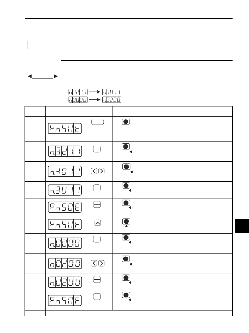
• Allocating Output Signals
The procedure to replace Movement Detection (/TGON) signal allocated to CN1-27 (28) with factory set-
ting to “Invalid” and allocate Brake Interlock (/BK) signal to CN1-27 (28) is shown below.
IMPORTANT
EXAMPLE
Step
Display after
Operation
Digital
Operator
Panel
Operator
Description
1
Press the DSPL/SET or MODE/SET Key to select the
“value setting parameter” mode. If a parameter other than
Pn50E is displayed, press the UP or DOWN Key to select
Pn50E.
Note: The enabled digit blinks.
2
Press the DATA/ENTER Key once, or DATA/SHIFT Key
for more than one second to display the current data of
Pn50E.
(/TGON is allocated to CN1-27 (28).)
3
Press the LEFT Key or RIGHT or DATA/SHIFT Key to
select the third digit from the right. Press the DOWN Key
to set “0.”
(Sets /TGON “Invalid.”)
4
Press the DATA/ENTER Key once, or DATA/SHIFT Key
for more than one second.
The value blinks and is saved.
5
Press the DATA/ENTER Key once, or DATA/SHIFT Key
for more than one second to return to the display Pn50E.
6
Press the UP Key to set Pn50F.
Note: The enabled digit blinks.
7
Press the DATA/ENTER Key once, or DATA/SHIFT Key
for more than one second to display the current data of
Pn50F.
(/BK is set to “Invalid.”)
8
Press the LEFT or RIHGT Key or DATA/SHIFT Key to
select the third digit from the right. Press the UP Key to set
“2.”
(Allocates /BK to CN1-27 (28).)
9
Press the DATA/ENTER Key once, or DATA/SHIFT Key
for more than one second. The value blinks and is saved.
10
Press the DATA/ENTER Key once, or DATA/SHIFT Key
for more than one second to return to the display Pn50F. /
TGON is set as “Invalid” and /BK is allocated to CN1-27
(28).
11
Turn OFF the power and ON again to enable the changes of output signal selection (Pn50E and Pn50F).
Pn50E:
Before
After
Pn50F:
DSPL
SET
(DSPL/SET Key)
MODE/SET
(MODE/SET Key)
DATA
ENTER
(DATA/ENTER
Key)
DATA/
(DATA/SHIFT Key)
DATA/
(DATA/SHIFT Key)
DATA
ENTER
(DATA/ENTER
Key)
DATA
(DATA/SHIFT Key)
(Press at least 1 s.)
DATA
ENTER
(DATA/ENTER
Key)
DATA
(DATA/SHIFT Key)
(Press at least 1 s.)
(UP Key)
(UP Key)
DATA
ENTER
(DATA/ENTER
Key)
DATA
(DATA/SHIFT Key)
(Press at least 1 s.)
DATA/
(DATA/SHIFT Key)
DATA
ENTER
(DATA/ENTER
Key)
DATA
(DATA/SHIFT Key)
(Press at least 1 s.)
DATA
ENTER
(DATA/ENTER
Key)
DATA
(DATA/SHIFT Key)
(Press at least 1 s.)