Yaskawa SGDH Linear Sigma Series User Manual
Page 109
4.4 SERVOPACK’s Power Supply Capacities and Power Losses
4-11
4
4.4 SERVOPACK’s Power Supply Capacities and Power Losses
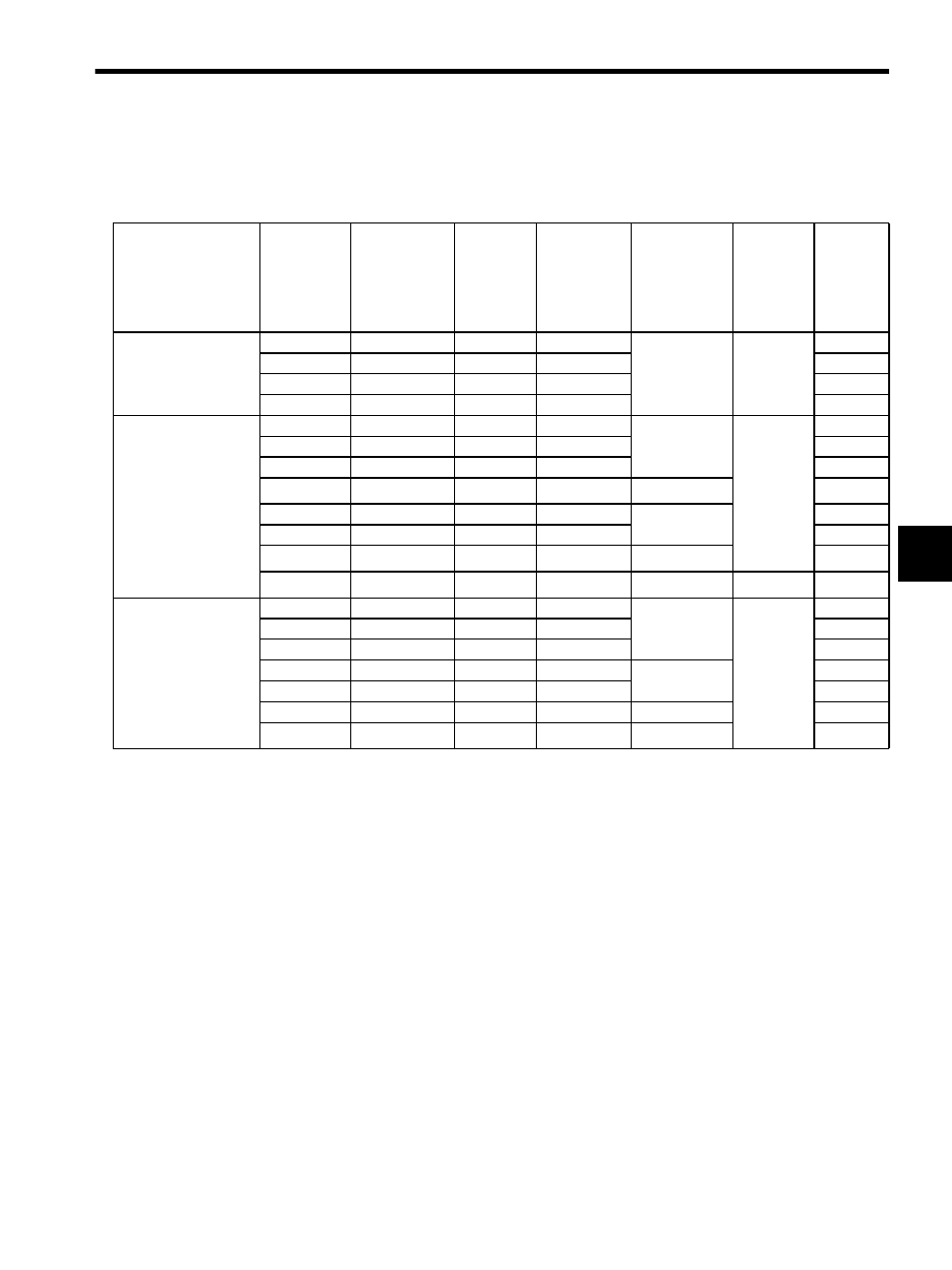
The following table shows SERVOPACK’s power supply capacities and power losses at the rated output.
* 1. SERVOPACKs with a capacity of 50 to 400W do not have built-in regenerative resistors. If the
regenerative energy exceeds the specified value, connect an external regenerative resistor. Refer to
11.1.3 Alarm Display Table when the Application Module is Used.
* 2. Regenerative resistor power losses are allowable losses. Take the following action if this value is
exceeded.
• Remove the lead from the internal regenerative resistor in the SERVOPACK.
• Install an external regenerative resistor (optional).
* 3. An external regenerative resistor must be connected to SERVOPACKs with a capacity of 7.5 kW.
The following regenerative resistor units are provided for this purpose.
For the SGDH-75DE: JUSP-RA18 (allowable loss: 180W)
For the SGDH-75AE: JUSP-RA05 (allowable loss: 350W)
Note: Refer to 7.6 Connecting Regenerative Resistors, 6.8.5 External Regenerative Resistor and 6.8.6
Regenerative Resistor for details.
Table 4.1 SERVOPACK Power Losses at Rated Output
Main Circuit Power
Supply
Maximum
Applicable
Linear Ser-
vomotor
Capacity
kW
SERVOPACK
Model
SGDH-
Output
Current
(Effective
Value)
A
Main Circuit
Power Loss
W
Regenerative
Resistor
Power Loss
W
Control
Circuit
Power
Loss
W
Total
Power
Loss
W
Single-phase 200 V
0.05
A5AE
0.64
4.6
−
∗1
13
17.6
0.10
01AE
0.91
6.7
19.7
0.20
02AE
2.1
13.3
26.3
0.40
04AE
2.8
20
33
Three-phase 200 V
0.45
05AE
3.8
27
12
∗2
15
54
0.75
08AE
5.7
41
68
1.0
10AE
7.6
55
82
1.5
15AE
11.6
92
14
∗2
121
2.0
20AE
18.5
120
28
∗2
163
3.0
30AE
24.8
155
198
5.0
50AE
32.9
240
56
∗2
311
7.5
75AE
54.7
330
−
∗3
27
357
Three-phase 400 V
0.45
05DE
1.9
19
14
∗2
15
48
1.0
10DE
3.5
35
64
1.5
15DE
5.4
53
82
2.0
20DE
8.4
83
28
∗2
126
3.0
30DE
11.9
118
161
5.0
50DE
16.5
192
36
243
7.5
75DE
25.4
264
−
∗3
279