Yaskawa SGDH Linear Sigma Series User Manual
Page 370
11 Inspection, Maintenance, and Troubleshooting
11.1.6 Troubleshooting for Malfunction without Alarm Display
11-18
Linear
Servomotor
Moves
Without
Reference
Input
Speed control: Speed reference input
is incorrect.
Check V-REF and SG to confirm if the con-
trol method and the input are agreed.
Correct the control mode selection parameter, or the
input correctly.
Force control: Force reference input
is incorrect.
Check T-REF and SG to confirm if the con-
trol method and the input are agreed.
Correct the control mode selection parameter, or the
input correctly.
Speed reference offset is error.
The SERVOPACK offset is adjusted incor-
rectly.
Adjust the SERVOPACK offset correctly.
Position control: Reference pulse
input is incorrect.
Check Pn200.0 reference pulse form or sign
+ pulse signal.
Correct the control mode selection parameter, or the
input correctly.
A SERVOPACK fault occurred.
A SERVOPACK board fault occurred.
Replace the SERVOPACK.
Linear scale counting up direction
and linear servomotor coil assembly
forward direction do not agree.
Check the directions.
Change the setting of Pn080.1 (Motor Phase Order
Selection).
Match the linear scale direction and servomotor direc-
tion.
Polarity detection is not performed
correctly.
Check if the value of Un004 (Electrical
Angle 2) at an arbitrary position is between
±
10 degrees.
Correct the polarity detection related parameter settings.
DB (dynamic
brake) Does
Not Operate
Improper parameter setting
Check the setting of parameter Pn001.0
(Servo OFF or Alarm Stop Mode).
Correct the setting of parameter Pn001.1.
DB resistor disconnected
Check if excessive mass, motor overspeed,
or DB frequently activated occurred.
Replace the SERVOPACK, and reconsider the load.
DB drive circuit fault
DB circuit parts are faulty.
Replace the SERVOPACK.
Abnormal
Noise from
Servomotor
Mounting not secured
Check if there are any loosen mounting
screws.
Tighten the mounting screws.
Vibration source on the driven
machine
Any foreign matter, damages, or deforma-
tion on the machine movable section.
Contact the machine manufacturer.
Noise interference due to incorrect
input signal wire specifications
The specifications of input signal wires
must be:
Twisted-pair or twisted-pair shielded wire
with core 0.12 mm
2
(0.0002 in
2
) min. and
tinned annealed copper twisted wire.
Use the specified input signal wires.
Noise interference due to long dis-
tance of input signal line
The wiring distance must be 3 m (9.84 ft)
max. and the impedance a few hundreds
ohm max.
Shorten the wiring distance for input signal line to the
specified value.
Noise interference due to incorrect
serial converter unit cable specifica-
tions
The specifications of encoder cable must
be:
Twisted-pair or twisted-pair shielded wire
with core 0.12 mm
2
(0.0002 in
2
) min. and
tinned annealed copper twisted wire.
Use the specified serial converter unit cable.
Noise interference due to long serial
converter unit cable wiring distance
The wiring distance must be 20 m(65.6 ft)
max.
Shorten the serial converter unit cable wiring distance to
the specified value.
Noise due to damaged serial con-
verter unit cable
Check if the serial converter unit cable is
not damaged or bent.
Modify the serial converter unit cable layout.
Excessive noise to the serial con-
verter unit cable
Check if the serial converter unit cable is
bundled with high-current line or near the
high-current line.
Install a surge suppressor to the serial converter unit
cable.
FG electrical potential varies by
influence of such machines on the
servomotor side as welders.
Check if the machine is correctly grounded.
Ground the machine separately from PG side FG.
SERVOPACK pulse counting error
due to noise
Check if there is noise interference on the
signal line from the serial converter unit.
Take measure against noise for the serial converter unit
wiring.
Excessive vibration and shock to the
serial converter unit
Vibration from the machine occurred or ser-
vomotor installation is incorrect.
(Mounting surface accuracy, fixing, or
alignment.)
Reduce vibration from the machine, or correct the linear
servomotor installation.
Serial converter unit fault
−
Replace the serial converter unit.
Linear scale fault
−
Replace the linear scale.
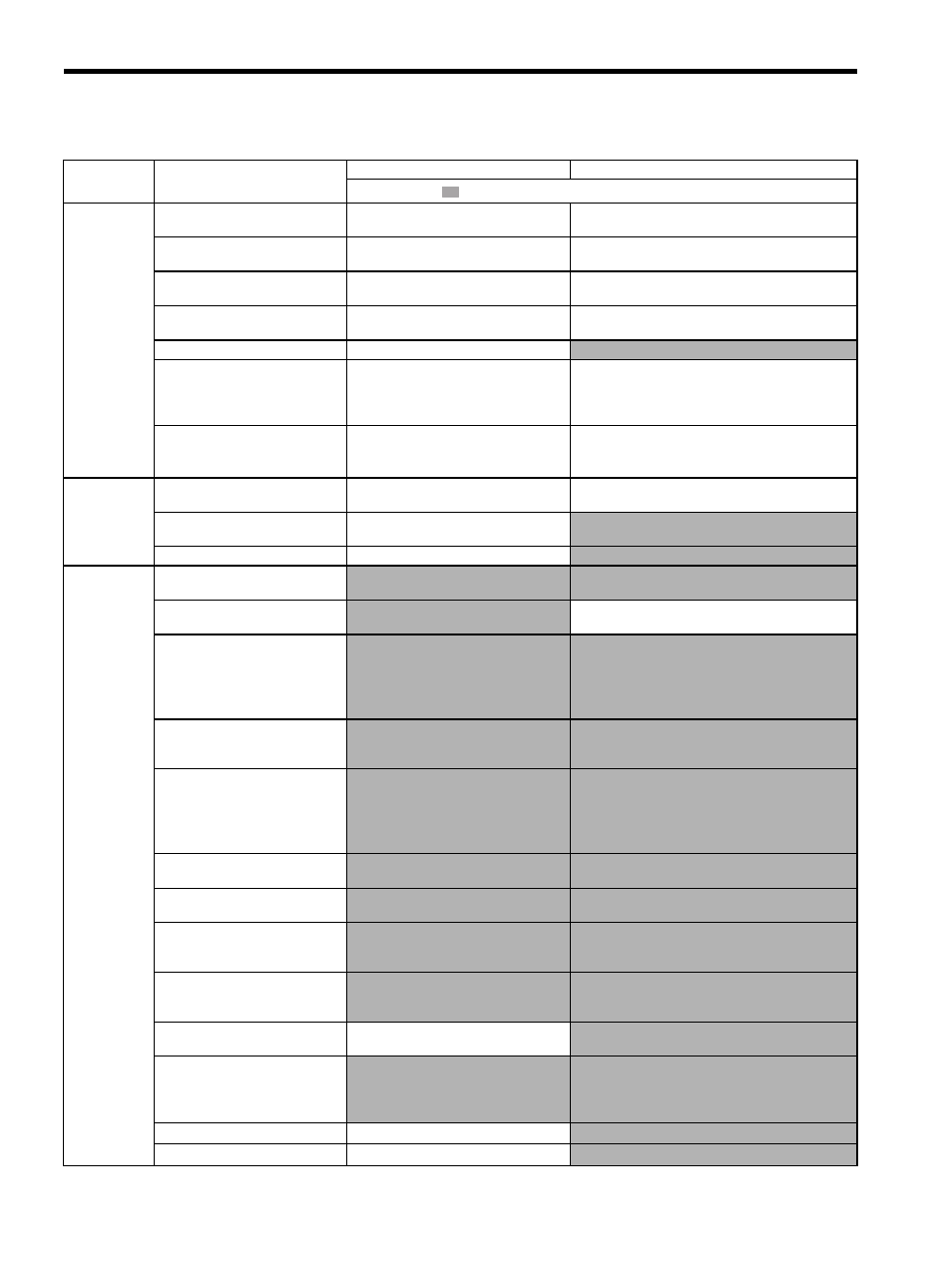
Table 11.7 Troubleshooting for Malfunction without Alarm Display (Cont’d)
Symptom
Cause
Inspection
Corrective Actions
: Turn OFF the servo system before executing operations.