Yaskawa SGDH Linear Sigma Series User Manual
Page 413
12.4 List of Parameters
12-37
12
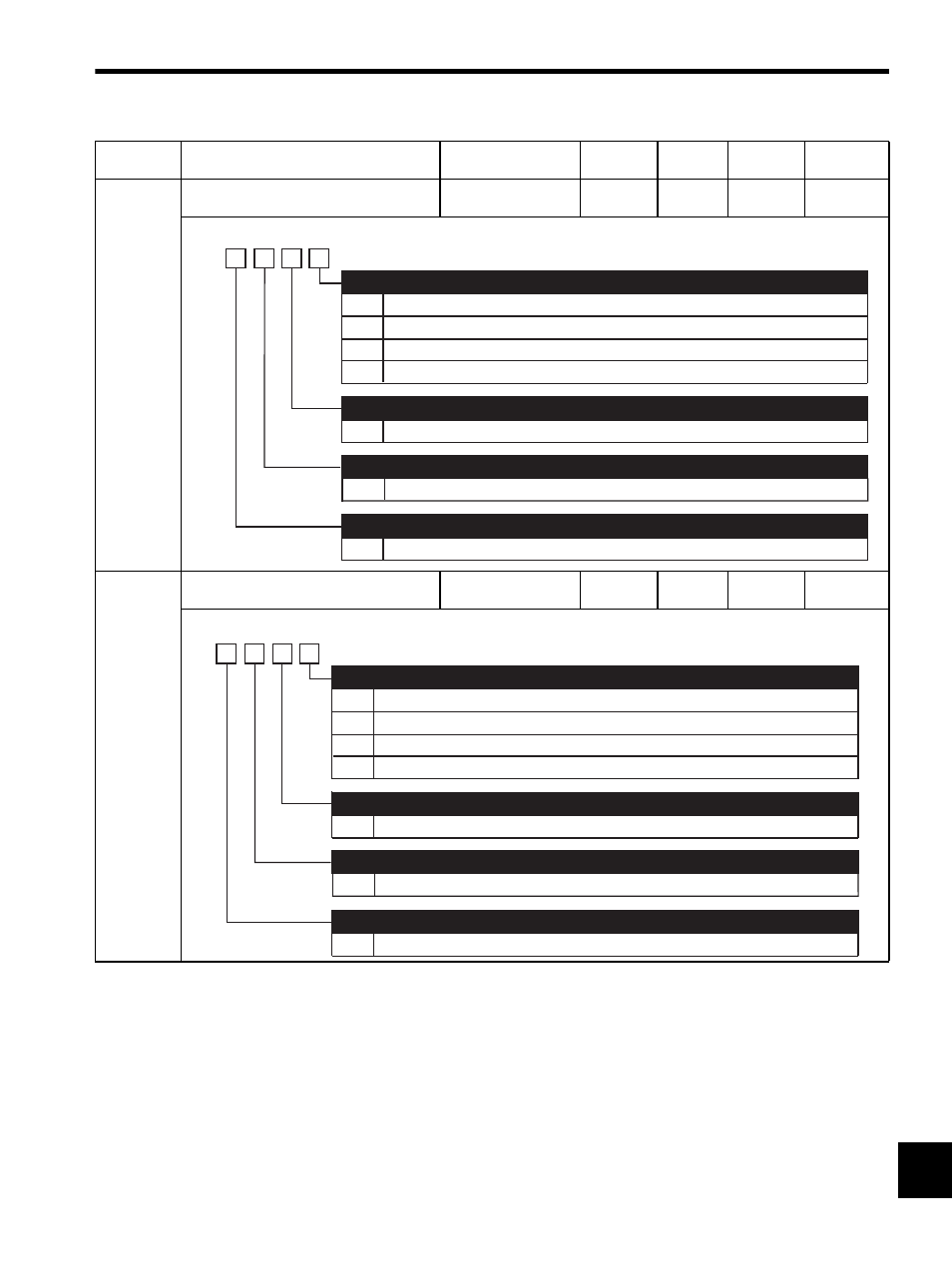
Pn50E
Output Signal Selection 1
−
−
3211
After
restart
−
Pn50F
Output Signal Selection 2
−
−
0000
After
restart
−
Parameter
No.
Name
Setting Range
Unit
Factory
Setting
Setting
Validation
Reference
Section
0
1
2
3
0 to 3
Disabled (the above signal is not used.)
Outputs the signal from CN1-25, -26 output terminal.
Outputs the signal from CN1-27, -28 output terminal.
Outputs the signal from CN1-29, -30 output terminal.
Same as /COIN
Same as /COIN
Same as /COIN
Positioning Completion Signal Mapping (/COIN)
(Refer to 9.8.5 Positioning Completed Output Signal.)
Speed Coincidence Detection Signal Mapping (/V-CMP)
(Refer to 9.7.8 Speed Coincidence Output.)
Movement Detection Signal Mapping (/TGON) (Refer to 9.13.3)
Servo Ready Signal Mapping (/S-RDY)
(Refer to 9.13.4 Servo Ready (/S-RDY) Output.)
4th
digit
3rd
digit
2nd
digit
1st
digit
n.
0 to 3
0 to 3
0
1
2
3
0 to 3
Disabled (the above signal is not used.)
Outputs the signal from CN1-25, -26 output terminal.
Outputs the signal from CN1-27, -28 output terminal.
Outputs the signal from CN1-29, -30 output terminal.
Same as /CLT
Same as /CLT
Same as /CLT
Force Limit Detection Signal Mapping (/CLT)
(Refer to 9.11.5 Checking Output Force Limiting during Operation.)
Speed Limit Detection Signal Mapping (/VLT)
(Refer to 9.9.4 Limiting Linear Servomotor Speed during Force Control.)
Brake Interlock Signal Mapping (/BK)
(Refer to 8.3.3 Setting for Holding Brakes.)
4th
digit
3rd
digit
2nd
digit
1st
digit
n.
0 to 3
0 to 3
Warning Signal Mapping (/WARN)
(Refer to 9.13.2 Warning Output (/WARN).)