Yaskawa SGDH Linear Sigma Series User Manual
Page 405
12.4 List of Parameters
12-29
12
Parameter
No.
Name
Setting Range
Unit
Factory
Setting
Setting
Validation
Reference
Section
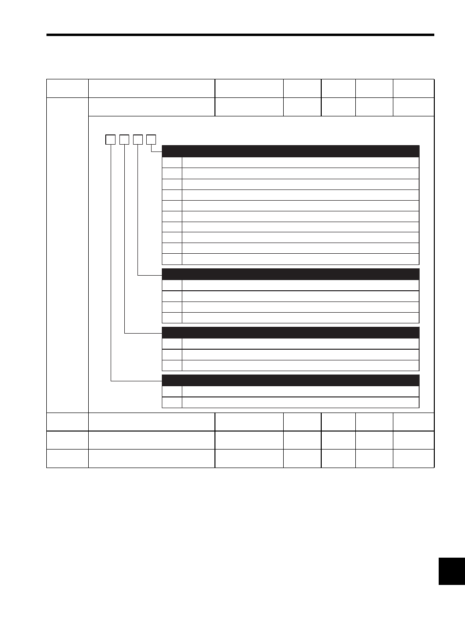
Pn200
Position Control Reference Form
Selection Switch
−
−
0000
After
restart
Pn202
Electronic Gear Ratio (Numerator)
1 to 65535
−
4
After
restart
Pn203
Electronic Gear Ratio (Denominator)
1 to 65535
−
1
After
restart
Pn204
Position Reference Accel/Decel Time
Constant
0 to 6400
0.01 ms
0
Immedi-
ately
0
1
2
3
4
5
6
7
8
9
Sign + Pulse, positive logic
CW + CCW, positive logic
Phase A + Phase B (
×1), positive logic
Phase A + Phase B (
×2), positive logic
Phase A + Phase B (
×4), positive logic
Sign + Pulse, negative logic
CW + CCW, negative logic
Phase A + Phase B (
×1), negative logic
Phase A + Phase B (
×2), negative logic
Phase A + Phase B (
×4), negative logic
Reference Pulse Form
0
1
2
3
Clears position error counter when the signal is at H level.
Clears position error counter at the rising edge of the signal.
Clears position error counter when the signal is at L level.
Clears position error counter at the falling edge of the signal.
Position Error Counter Clear Signal Form
4th
digit
3rd
digit
2nd
digit
1st
digit
n.
0
1
2
Clear error counter at the baseblock.
Does not clear error counter. (Possible to clear error counter only with CLR signal.)
Clear error counter when an alarm occurs.
Clear Operation
0
1
Reference input filter for line driver signals
Reference input filter for open collector signals
Filter Selection