Yaskawa SGDH Linear Sigma Series User Manual
Page 365
11.1 Troubleshooting
11-13
11
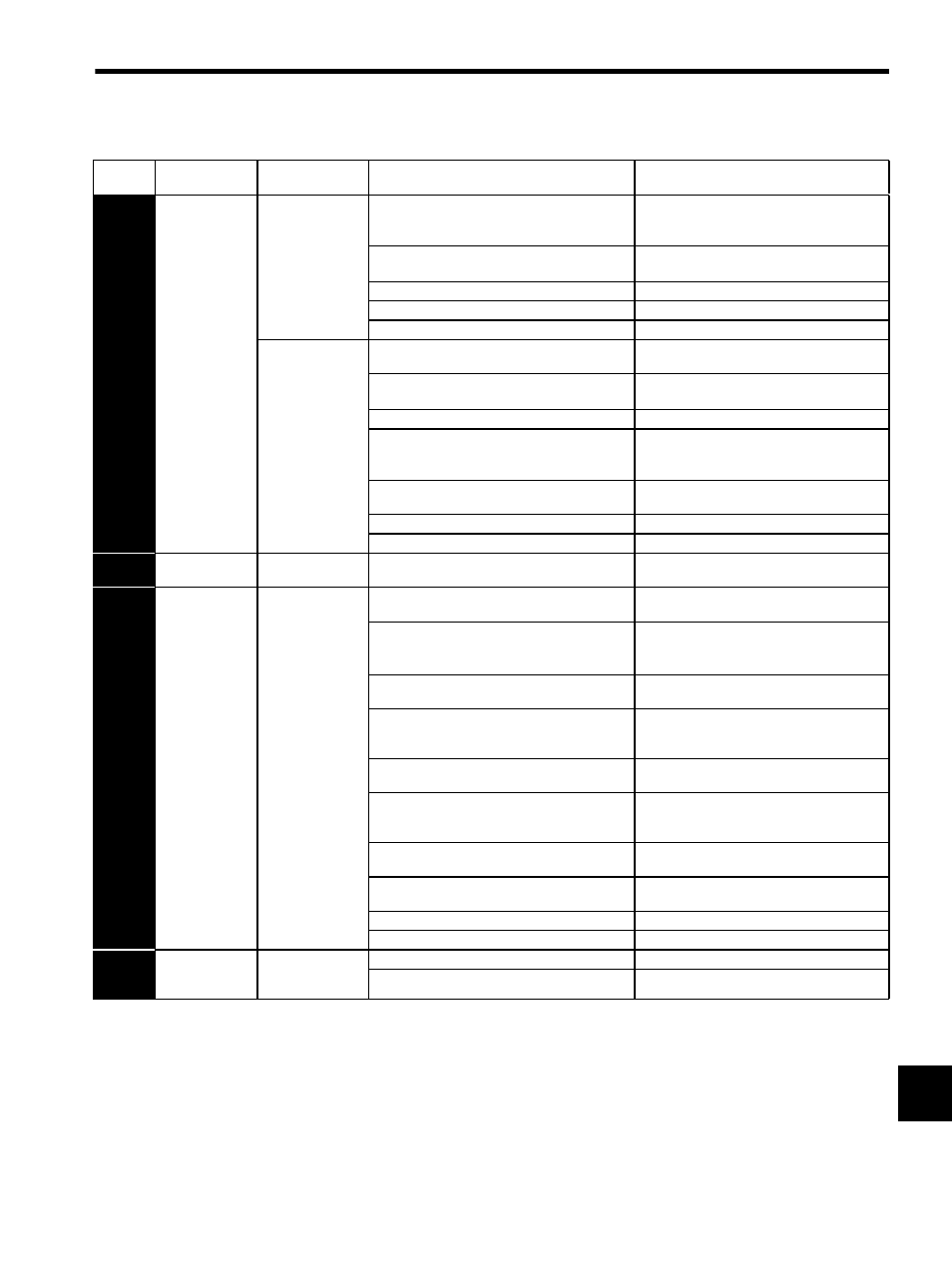
A.C2
Phase Faulty
Detection
(Occurs when
using a hall
sensor.)
Occurred when the
control power sup-
ply was turned ON.
When Pn080.0 = 0 is set though no hall sensor is
mounted.
Connect correctly the hall sensor cable to the
serial converter unit.
Correct the setting of parameter Pn080.0.
The hall sensor is protruding from the linear servo-
motor magnetic way.
Reconsider the linear servomotor installation.
A hall sensor fault occurred.
Replace the linear servomotor coil assembly.
A serial converter unit fault occurred.
Replace the serial converter unit.
A SERVOPACK fault occurred.
Replace the SERVOPACK.
Occurred when the
servo is turned ON
or during operation.
The linear servomotor coil assembly direction and
linear scale direction do not match.
Correct the setting of parameter Pn080.1.
The hall sensor is protruding from the linear servo-
motor magnetic way.
Reconsider the linear servomotor installation.
The value set for Pn280 is incorrect.
Correct the set value of Pn280.
Noise interference on the hall sensor signals
Take a noise prevention measure for the hall sen-
sor wiring.
Connect the case of serial converter unit to FG.
The linear scale installation does not meet the
requirements of the scale specifications.
Reconsider the installation.
Dust and dirt accumulate on the linear scale.
Remove dust and dirt on the linear scale.
A linear scale fault occurred.
Replace the linear scale.
A.C5
Polarity
Detection Faulty
Occurred during
polarity detection.
The polarity detection failed.
Refer to 9.2.3 (d) Troubleshooting for Polarity
Detection Errors.
A.C9
Encoder
Communica-
tions Error
Occurred when the
control power sup-
ply was turned ON
or during operation.
The serial converter unit wiring and the contact are
incorrect.
Correct the serial converter unit wiring.
Noise interference occurred due to incorrect serial
converter unit cable specifications.
Use tinned annealed copper twisted-pair or
twisted-pair shielded wire with a core of at least
0.12 mm
2
(0.0002 in
2
).
Noise interference occurred because the wiring dis-
tance for the serial converter unit cable is too long.
The wiring distance must be 20m (65.6 ft) max.
The noise interference occurred on the signal line
because the serial converter unit cable is bent and
the sheath is damaged.
Correct the serial converter unit cable layout.
The serial converter unit cable is bundled with a
high-current line or near a high-current line.
Correct the serial converter unit cable layout so
that no surge is applied.
The FG electrical potential varies because of the
influence from such machines on the servomotor
side as welders.
Ground the machine separately from PG side FG.
Noise interference occurred on the signal line from
the serial converter unit.
Take a measure against noise for the serial con-
verter unit wiring.
Excessive vibration and shocks were applied to the
serial converter unit.
Reduce the machine vibration or mount the serial
converter unit securely.
A serial converter unit fault occurred.
Replace the serial converter unit.
A SERVOPACK board fault occurred.
Replace the SERVOPACK.
A.CA
Encoder
Parameter Error
Occurred when the
control power sup-
ply was turned ON.
A serial converter unit fault occurred.
Replace the serial converter unit.
A SERVOPACK board fault occurred.
Replace the SERVOPACK.
Table 11.5 Alarm Display and Troubleshooting (Cont’d)
Alarm
Display
Alarm Name
Situation at Alarm
Occurrence
Cause
Corrective Actions