2 servo gain manual tuning, 3 position loop gain – Yaskawa SGDH Linear Sigma Series User Manual
Page 335
10.3 Manual Tuning
10-13
10
10.3.2 Servo Gain Manual Tuning
The SERVOPACK has the following parameters for the servo gains. Setting the servo gains in the parameters
can adjust the servo responsiveness.
• Pn100: Speed loop gain (Kv)
• Pn101: Speed loop integral time constant (Ti)
• Pn102: Position loop gain (Kp)
• Pn401: Force reference filter time constant (Tf)
For the position and speed control, the adjustment in the following procedure can increase the responsiveness.
The positioning time in position control can be reduced.
Perform the manual tuning in the following cases.
• To increase the servo gains more than the values set by the online autotuning.
• To determine the servo gains and mass ratio by the user.
Start the manual tuning from the factory setting or the values set by the online autotuning. Prepare measuring
instruments such as memory recorder so that the signals can be observed from the analog monitor (CN5) such as
“Force Reference” and “Motor Speed,” and “Position Error Monitor” for the position control. (Refer to 10.5
Analog Monitor.) The servodrive supporting tool “SigmaWin+” allows you to observe such signals. Prepare
either of them.
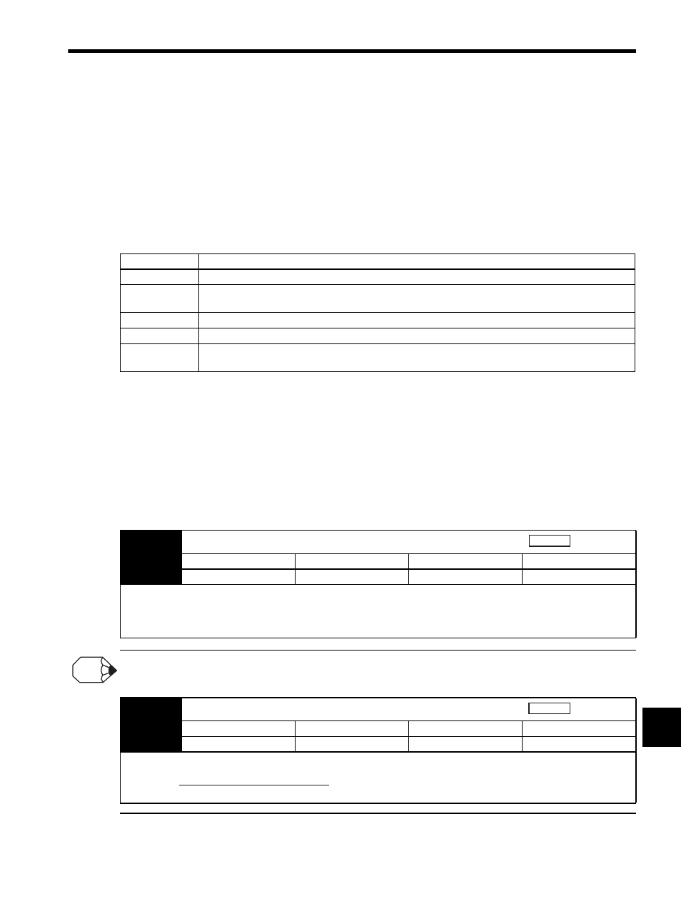
10.3.3 Position Loop Gain
If the position loop gain (Pn102) cannot be set high in the mechanical system, an overflow alarm may occur during high
speed operation. In this case, increase the values in the following parameter to suppress detection of the overflow alarm.
Step
Explanation
1
Set correctly the mass ratio (Pn103). The utility function Fn007 can be used after the online autotuning.
2
Increase the speed loop gain (Pn100) to within the range so that the machine does not vibrate. At the
same time, decrease the speed loop integral time constant (Pn101).
3
Adjust the force reference filter time constant (Pn401) so that no vibration occurs.
4
Repeat the steps 1 and 2. Then reduce the value for 10 to 20%.
5
For the position control, increase the position loop gain (Pn102) to within the range so that the machine
does not vibrate.
Pn102
Position Loop Gain (Kp)
Setting Range
Setting Unit
Factory Setting
Setting Validation
1 to 2,000
1/s
40
Immediately
The responsiveness of the position loop is determined by the position loop gain. The responsiveness increases and the posi-
tioning time decreases when the position loop gain is set to a higher value. In general, the position loop gain cannot be set
higher than natural vibrating frequency of the mechanical system, so the mechanical system must be made more rigid to
increase its natural vibrating frequency and allow the position loop gain to be set to a high value.
Position
INFO
Pn505
Overflow Level
Setting Range
Setting Unit
Factory Setting
Setting Validation
1 to 32,767
256 reference units
1,024
Immediately
This parameter’s new setting must satisfy the following condition.
Position
Pn505
Pn102
2.0
≥ Max. feed speed (reference units/s) ×