5 troubleshooting of alarm and warning, 5 troubleshooting of alarm and warning -7, 1) alarm display and troubleshooting – Yaskawa SGDH Linear Sigma Series User Manual
Page 359
11.1 Troubleshooting
11-7
11
11.1.5 Troubleshooting of Alarm and Warning
When an error occurs in servodrive, an alarm display such as A. and CPF or warning display such as
A.9 appears on the panel operator. However, the display “A.--” is not an alarm. Refer to the following sec-
tions to identify the cause of an alarm and the action to be taken.
Contact your Yaskawa representative if the problem cannot be solved by the described corrective action.
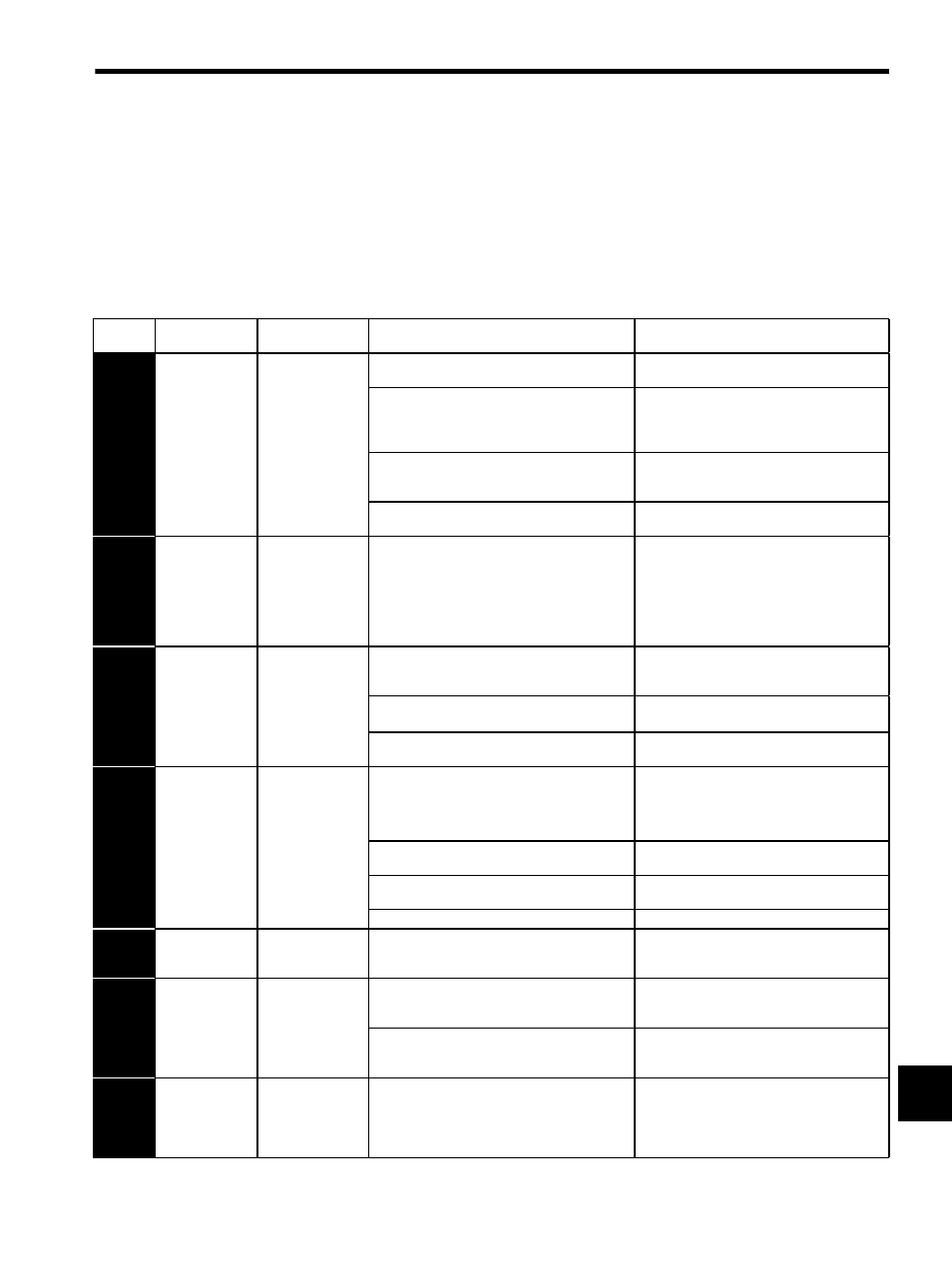
(1) Alarm Display and Troubleshooting
Table 11.5 Alarm Display and Troubleshooting
Alarm
Display
Alarm Name
Situation at Alarm
Occurrence
Cause
Corrective Actions
A.02
Parameter
Breakdown
(The EEPROM
data storing the
parameter is
incorrect.)
Occurred when the
control power sup-
ply was turned ON.
The control power supply ranged from 30 VAC to
60 VAC.
Correct the power supply, and set Fn005 to initial-
ize the parameter.
The power supply was turned OFF while changing
the parameter setting.
The power supply was turned OFF while an alarm
was being written.
Set Fn005 to initialize the parameter and input the
parameter again.
The number of times that parameters were written
exceeded the limit. For example, the parameter was
changed every scan through the host controller.
Replace the SERVOPACK.
(Recheck the parameter writing method.)
The SERVOPACK EEPROM and the related circuit
are faulty.
Replace the SERVOPACK.
A.03
Main Circuit
Encoder Error
(Not detected for
the SERVO-
PACK with the
capacity of 7.5
kW)
Occurred when the
control power sup-
ply was turned ON
or during operation
The control power supply ranged from 30 VAC to
60 VAC.
A SERVOPACK fault occurred.
Correct the power supply.
Replace the SERVOPACK.
A.04
Parameter
Setting Error
(The parameter
setting was out of
the allowable set-
ting range.)
Occurred when the
control power sup-
ply was turned ON.
The incorrect parameter was being loaded. (The
incorrect value was rejected as an error at the digital
operator.)
Set Fn005 to initialize the parameter.
Pn080.0 = 1 was set though a hall sensor was con-
nected.
Check and correct the hall sensor wiring.
Correct the set value of parameter Pn080.0.
The SERVOPACK EEPROM and the related circuit
are faulty.
Replace the SERVOPACK.
A.05
Combination
Error
(The SERVO-
PACK and servo-
motor capacities
do not corre-
spond.)
Occurred when the
control power sup-
ply was turned ON.
The SERVOPACK and servomotor capacities do not
correspond to each other.
Servomotor capacity / SERVOPACK capacity
≤
1/4
or servomotor capacity / SERVOPACK capacity
≥
4
Select the proper combination of SERVOPACK
and servomotor capacities.
The linear servomotor and SERVOPACK voltage
specifications do not correspond to each other.
Select the proper combination of SERVOPACK
and linear servomotor voltages.
The parameter that is written in the serial converter
unit is incorrect.
Replace the serial converter unit.
A SERVOPACK board fault occurred.
Replace the SERVOPACK.
A.08
Linear Scale
Pitch Setting
Error
Occurred when the
control power sup-
ply was turned ON.
The initial value is set for Pn280.
Correct the set value of parameter Pn280.
A.09
Dividing Ratio
Setting Error
(For the software
version 32 or
later)
Occurred when the
control power sup-
ply was turned ON.
A value higher than the motor peak speed that can be
obtained from the dividing ratio was set for Pn384.
Change the set value to a value within the allow-
able peak speed, referring to Un010.
Then set validation of the control power supply.
A value higher than the maximum dividing ratio that
can be obtained from the linear servomotor peak
speed was set for Pn281.
Change the set value to a value within the allow-
able dividing ratio, referring to Un010.
Then set validation of the control power supply.
A.0A
Encoder Type
Mismatching
(For the software
version 32 or
later)
Occurred when the
control power sup-
ply was turned ON.
The mounted serial encoder is not supported by
∑-II
series.
Replace the linear servomotor with the
∑-II series
supported model.