7 encoder signal output, 7 encoder signal output -43, Important – Yaskawa SGDH Linear Sigma Series User Manual
Page 287
9.7 Operating Using Speed Control with Analog Reference
9-43
9
9.7.7 Encoder Signal Output
Encoder feedback pulses processed inside the SERVOPACK can be output externally.
• When returning the machine to its home position by using the zero-point signal of linear scale, the home
return speed should be 50 mm/s or less. If the speed is higher than 50 mm/s, the phase C pulse may not be
output correctly.
• When using a linear scale with more than one zero-point signal, the phase C pulse width of 2nd and onward
zero-point signal will be half of the phase A pulse width.
Dividing
The dividing means that the divider converts data into the pulse density set in the parameter Pn281, on the base of the scale
pitch of linear scale installed on the linear servomotor, and outputs it. The setting unit is the number of edges/scale pitch.
Type
Signal
Name
Connector
Pin Number
Name
Output
PAO
CN1-33
Encoder output phase A
/PAO
CN1-34
Encoder output phase /A
Output
PBO
CN1-35
Encoder output phase B
/PBO
CN1-36
Encoder output phase /B
Output
PCO
CN1-19
Encoder output phase C (zero-point pulse)
/PCO
CN1-20
Encoder output phase /C (zero-point pulse)
* Even in reverse movement mode (Pn000.0 = 1), the dividing output phase form is the same as that for the standard setting
(Pn000.0 = 0).
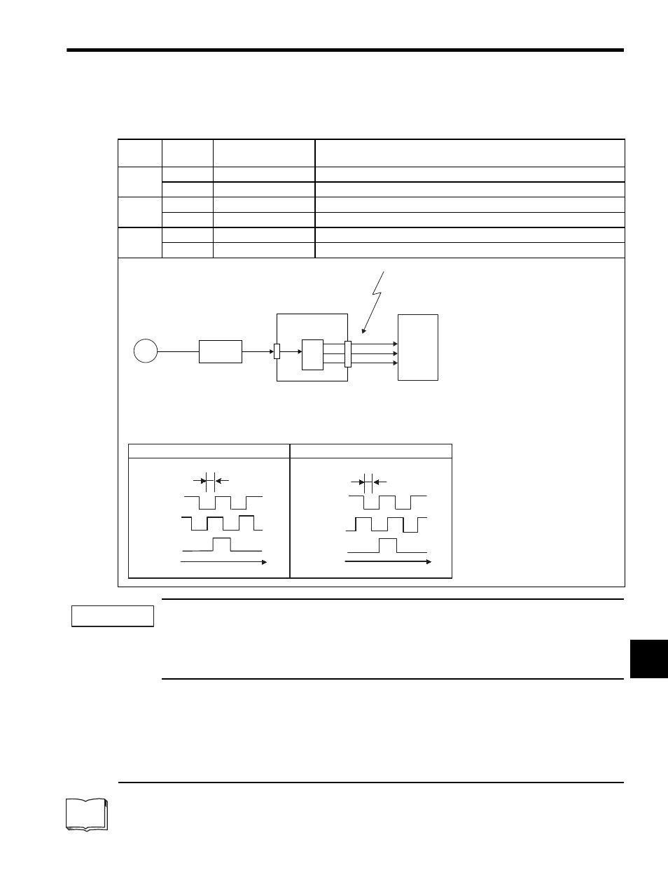
Output Phase Form
PG
SERVOPACK
CN2
CN1
Linear
scale
Host controller
Outputs are explained here.
Phase A (PAO)
Phase B (PBO)
Phase C (PCO)
DATA
Analog signal
Fre-
quency
dividing
circuit
∗
Note: The zero-point pulse width will
be the same as the phase A
pulse width accoding to the
dividing ratio.
Serial
converter
unit
Phase A
Phase B
Phase C
90
°
t
Phase A
Phase B
Phase C
90
°
t
Forward movement (phase B leads by 90
°) Reverse movement (phase A leads by 90°)
IMPORTANT
TERMS