6) jog operation from the panel operator – Yaskawa SGDH Linear Sigma Series User Manual
Page 254
9 Operation
9.2.2 Setup Procedure Using Linear Servomotors with Hall Sensors
9-10
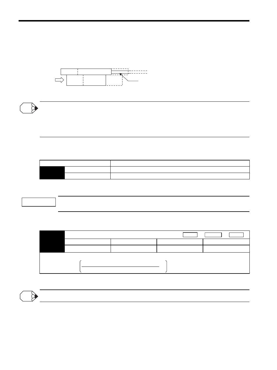
(b) Checking the Concurrence between the Linear Scale Count Direction and the Linear Ser-
vomotor Forward Direction
Next, move the coil assembly by hand in the direction of the side with the cable, and check that the Un00D
monitor is counting up.
When the Value of the Un00D is counted down
When the value of the Un00D is a counted down, set the parameter Pn080.1 = 1 (B-phase progression, U, V, W-phase in
order). Enable the setting by setting validation.
With this setting, the SERVOPACK performs current control by treating the linear scale countup direction as the motor
forward direction.
(c) Related Parameters
Pn080.1 is available for software version 32 or later.
(6) Jog Operation from the Panel Operator
When turning ON the servo for the first time after installation and wiring, stand away from the motor mov-
ing part as overrun may occur.
1. To perform a trial operation with a load attached, set mass ratio (Pn103) before running.
When the calculated mass ratio exceeds 20000%, set 20000 in the parameter and adjust loop gains.
* This setting range is applicable for software version 32 or later. The range for software earlier than ver-
sion 32 is 0% to 10,000%.
Perform trial operations without a load attached, where possible.
2. Turn ON the control power supply and main circuit power supply.
3. Operate the panel operator or digital operator and move the linear servomotor using jog operation. For
details on jog operation, refer to 8.2.3 JOG Mode Operation (Fn002).
4. Check that the linear servomotor moves normally from end to end of the stroke.
When the linear servomotor is moved by hand to the side with the cable,
if the value of Un00D is a countup value, confirmation is completed.
Linear servomotor cable
attached to coil assembly
INFO
Parameter
Description
Pn080
n.0
Phase-A progression, phase-U, V, W order (factory setting)
n.1
Phase-B progression, phase-U, V, W order
IMPORTANT
Pn103
Mass Ratio
Setting Range
Setting Unit
Factory Setting
Setting Validation
0 to 20000 %
∗
1 %
0 %
Immediately
Use the following formula to obtain the mass ratio.
Speed
Position
Force
Mass ratio (Pn103) =
Coil assembly mass
Load mass (including mass of coil assembly) −1 × 100 [%]
INFO