1 sglgo-30 linear servomotors, 1 sglg, 1 sglg-30 linear servomotors -17 – Yaskawa SGDH Linear Sigma Series User Manual
Page 65: 1 sglg-30 linear servomotors
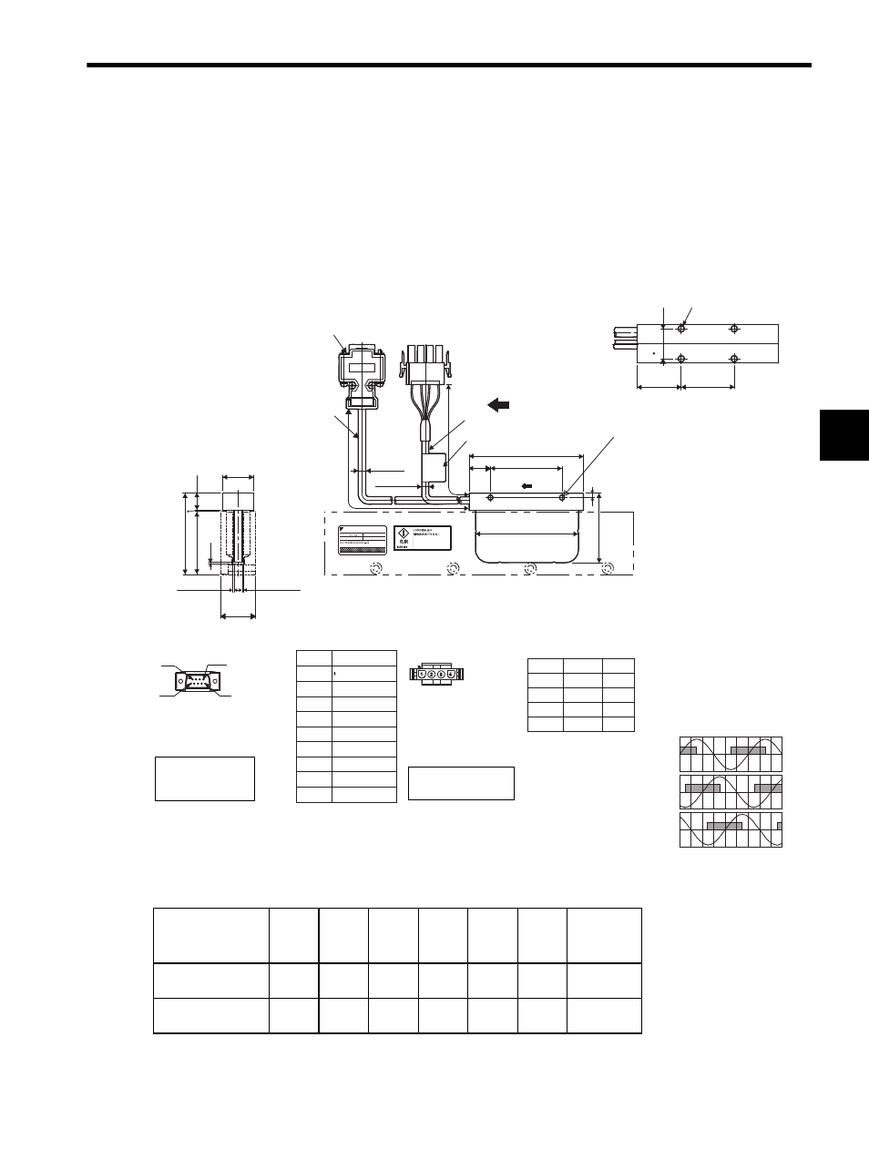
3.6 Dimensional Drawings of SGLGW/SGLGM Linear Servomotors
3-17
3
3.6 Dimensional Drawings of SGLGW/SGLGM Linear Servomotors
3.6.1 SGLG-30 Linear Servomotors
(1) Coil Assembly: SGLGW-30AC
With a connector made by Tyco Electronics AMP K.K.
The following table and figures show the specifications when a main circuit’s cable connector made by Tyco
Electronics is used for the coil assembly.
* The value indicates the mass of coil assembly with a hall sensor unit.
Coil Assembly
Model SGLGW-
L1
L2
L3
L4
L5
G
(Gap)
Approx.
Mass
∗
kg (lb)
30A050C
50
(1.97)
48
(1.89)
30
(1.18)
20
(0.79)
20
(0.79)
0.85
(0.03)
0.14
(0.31)
30A080C
80
(3.15)
72
(2.83)
50
(1.97)
30
(1.18)
25
(0.98)
0.95
(0.04)
0.19
(0.42)
Hall Sensor
Connector Specifications
9
6
1
5
Pin connector type:
17JE-23090-02 (D8C)
made by DDK Ltd.
The mating connector
Socket connector type:
17JE-13090-02 (D8C)
Stud type:17L-002C or
17L-002C1
Pin No.
1
2
3
4
5
6
7
8
9
Name
5V (Power supply)
Phase U
Phase V
Phase W
0V (Power supply)
Not used
Not used
Not used
Not used
Linear Servomotor
Connector Specifications
Plug type: 350779-1
Pin type: 350924-1 or
770672-1
made by Tyco
Electronics AMP K.K.
The mating connector
Cap type: 350780-1
Socket type: 350925-1 or
770673-1
Hall Sensor Output Signals
Electrical angle (
° )
Vu
Vv
Vw
Su
Sv
Sw
0
180
360
540
The coil assembly moves in the direction indicated by the arrow
when current flows in the order of phase U, V, and W.
A
W
Ins.
L5
L4
away.
May cause injury.
Keep magnetic materials
YASKAWA ELECTRIC CORPORATION JAPAN
N
2
×screw
#4-40 UNC
UL2517,AWG25
Cable
UL20276,AWG26
2
×2-M4
Mounting screw depth: 5 (0.20) on both sides
500
±50
(19.69
±1.97
)
500
±50
(19.69
±1.97
)
L1
L3
L2
G (Gap)
G (Gap)
Cable
Nameplate
When the coil assembly moves in the
direction indicated by the arrow in the
figure, the relationship between the hall
sensor output signals Su, Sv, Sw and
the inverse power of each motor phase
Vu, Vv, Vw becomes as shown in the
following figure.
Pin No.
1
2
3
4
Name
Phase U
Phase V
Phase W
FG
Red
White
Blue
Green
Inverse
power
(V)
Lead
Color
22 (0.87)
12 (0.47)
57 (2.24)*
44 (1.73)
1 (0.04)
24 (0.94)
φ5.3
(
φ0.21)*
φ5 (0.20)*
48.5 (1.91)
3
(0.12)
* Reference length
Units: mm (in)
4
×M4 mounting screw,
depth 5 (0.20)
17 (0.67)
15 (0.59)