2) coil assembly installation – Yaskawa SGDH Linear Sigma Series User Manual
Page 173
7.1 Linear Servomotor Installation
7-9
7
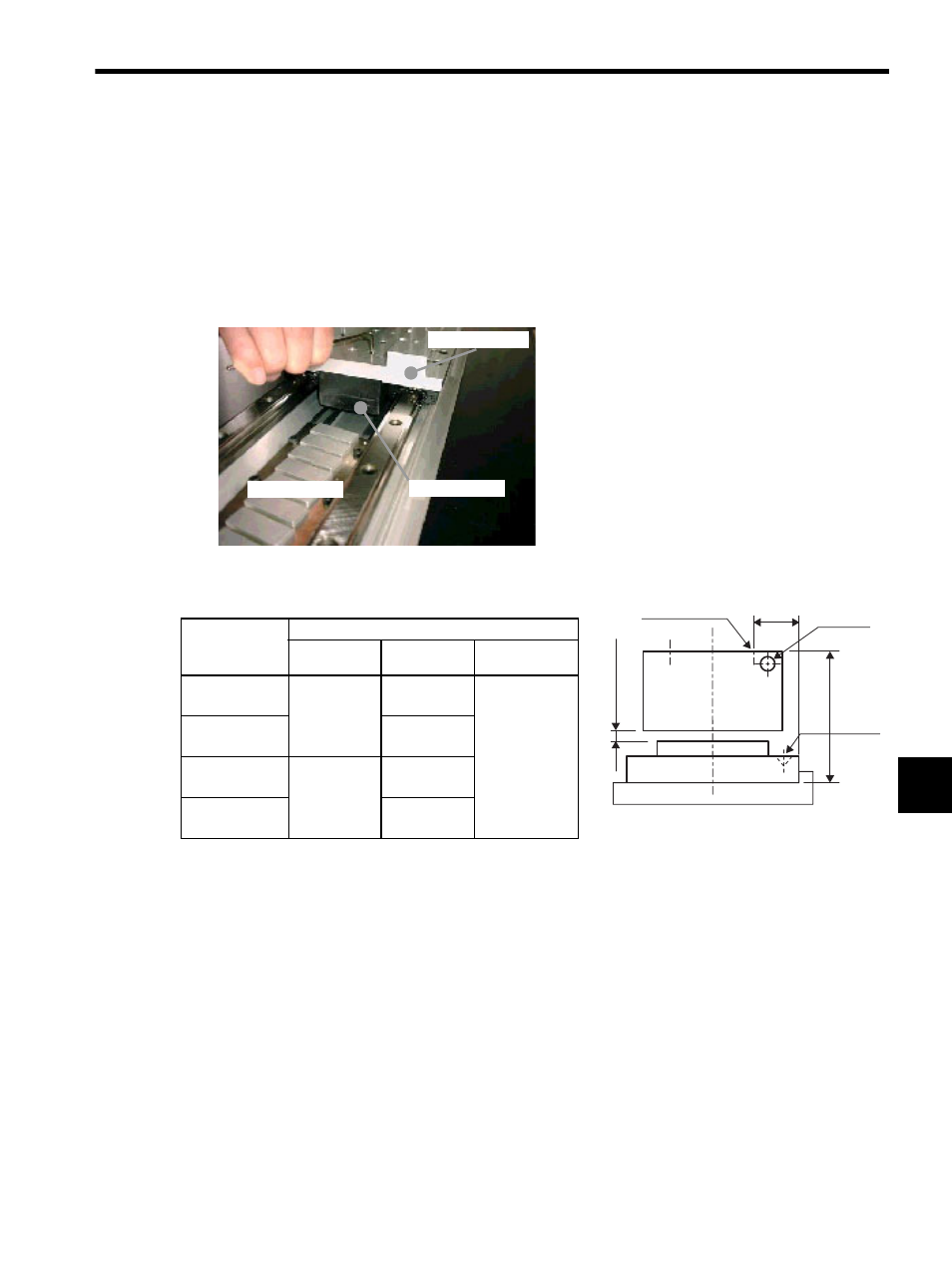
(2) Coil Assembly Installation
The SGLFW coil assembly is constructed of an aluminum or steel base and iron core, with a resin-coated coil
winding section. Make sure that the coil winding section is not subjected to shock during installation. Shock may
cause injury or damage to the coil assembly.
Use the following procedure to install the SGLFW coil assembly.
1. Install the coil assembly on the movable table supported by the linear guide in line with the previously
installed magnetic way.
Make sure that the air gap between the coil assembly and magnetic way magnets is the specified distance.
Maintain the following air gaps when installing. Make sure that the coil assembly and magnetic way do
not interfere during the stroke.
* The value in parentheses is the dimension when the magnet protection
cover is used.
Coil Assembly
Model
SGLFW-
Dimensions is mm (in)
H
P
Air gap G
20
45
± 0.1
(1.77
± 0.004)
22
± 0.2
(0.87
± 0.004)
1
±
0.3
(0.04
± 0.01)
(0.8 (0.03))
∗
35
21
± 0.2
(0.83
± 0.004)
50
58
± 0.1
(2.28
± 0.004)
25.8
± 0.2
(1.02
± 0.004)
1Z
27
± 0.2
(1.06
± 0.004)
Magnetic way
Coil assembly
Movable table
Air gap G
H
P
Coil
assembly
Magnetic way
Installation tap
Linear servomotor side
(Diagram viewed from the side where the
cable extends from the coil assembly.)
Cable
Standard
mark