4 sglto-40 linear servomotors, 4 sglt, 40 linear servomotors -43 – Yaskawa SGDH Linear Sigma Series User Manual
Page 91: 4 sglt-40 linear servomotors, 1) coil assembly: sgltw-40b
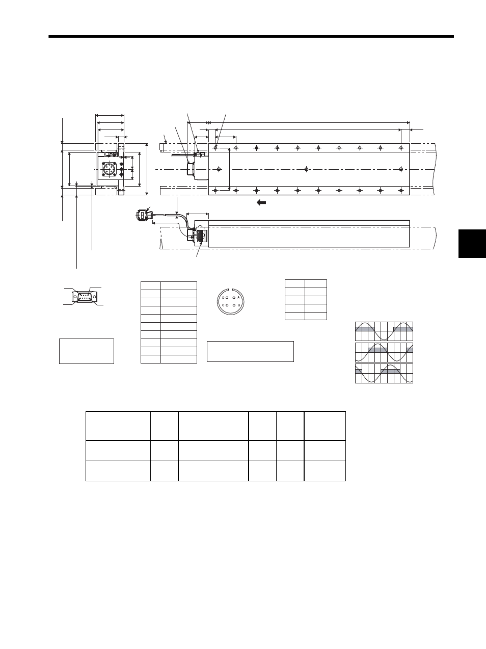
3.8 Dimensional Drawings of SGLTW / SGLTM Linear Servomotors
3-43
3
3.8.4 SGLT-40 Linear Servomotors
(1) Coil Assembly: SGLTW-40B
* Reference length
N
m/s
Linear SERVO MOTOR
ins.
DATE
S/N
O/N
V
A
W
MADE IN JAPAN
YASKAWA ELECTRIC
TYPE
(L3)
L1
L2
64 min.
124 (4.88)
The coil assembly moves in the direction indicated by the arrow when
current flows in the order of phase U, V, and W.
Magnetic way
Receptacle
Hall sensor
2
×screws
#4-40 UNC
N
×M8 tapped holes, depth 16 mm
Nameplate
Inverse
power
(V)
97 (3.82)
111.8 (4.40)*
19.1 (0.75)*
(25.3 (1.0): With magnet protection cover)
(25.1 (0.99): Without magnet protection cover)
(Gap 1.2 (0.05): With magnet
protection cover)
(Gap 1.4 (0.06): Without magnet
protection cover)
83 (3.27)*
78 (3.07)
75 (2.95)
16
(0.63)
1 (0.04)
38
(1.50)
30
(1.18)
98 (3.86)
150 (5.91)
φ
4.2
(φ
0.17)
500
±50
(19.69
±1.97
)
63 (2.48)
40
(1.57)
60 (2.36)
* Reference length
Units: mm (in)
20 (0.79)
Receptacle type: MS3102A-22-22P
made by DDK Ltd.
The mating connector
L-shaped plug type: MS3108B22-22S
Straight plug type: MS3106B22-22S
Cable clamp type: MS3057-12A
Hall Sensor
Connector Specifications
9
6
1
5
Pin connector type:
17JE-23090-02(D8C)
made by DDK Ltd.
The mating connector
Socket connector type:
17JE-13090-02(D8C)
Stud type: 17L-002C or
ޓޓޓޓޓ17L-002C1
Pin No.
1
2
3
4
5
6
7
8
9
Name
㧗5V (Power supply)
Phase U
Phase V
Phase W
0V (Power supply)
Not used
Not used
Not used
Not used
Linear Servomotor
Connector Specifications
Pin No.
A
B
C
D
Name
Phase U
Phase V
Phase W
Ground
Hall Sensor Output Signals
Electrical angle(
° )
Vu
Vv
Vw
Su
Sv
Sw
0
180
360
540
When the coil assembly moves in the di-
rection indicated by the arrow in the fig-
ure, the relationship between the hall
sensor output signals Su, Sv, Sw, and
the inverse power of each motor phase
Vu, Vv, Vw becomes as shown in the fig-
ure below.
19.1 (0.75)*
Coil Assembly
Model SGLTW-
L1
L2
L3*
N
Approx.
Mass
kg (lb)
40400B
395
(15.55)
360 (14.17)
(60 (2.36)
× 6 (0.24))
15
(0.59)
14
(0.55)
20
(44.09)
40600B
585
(23.03)
540 (21.26)
(60 (2.36)
× 9 (0.35))
25
(0.98)
20
(0.79)
30
(66.14)