2 forward or filter, 2 forward or filter -2 – PLANET XGS3-24042 User Manual
Page 147
16-2
The topology of the figure above: 4 PCs connected to switch, where PC1 and PC2 belongs to a same physical
segment (same collision domain), the physical segment connects to port 1/0/5 of switch; PC3 and PC4
belongs to the same physical segment that connects to port 1/0/12 of switch.
The initial MAC table contains no address mapping entries. Take the communication of PC1 and PC3 as an
example, the MAC address learning process is as follow:
1.
When PC1 sends message to PC3, the switch receives the source MAC address
00-01-11-11-11-11 from this message, the mapping entry of 00-01-11-11-11-11 and port 1/0/5 is
added to the switch MAC table.
2.
At the same time, the switch learns the message is destined to 00-01-33-33-33-33, as the MAC
table contains only a mapping entry of MAC address 00-01-11-11-11-11 and port1/0/5, and no port
mapping for 00-01-33-33-33-33 present, the switch broadcast this message to all the ports in the
switch (assuming all ports belong to the default VLAN1).
3.
PC3 and PC4 on port 1/0/12 receive the message sent by PC1, but PC4 will not reply, as the
destination MAC address is 00-01-33-33-33-33, only PC3 will reply to PC1. When port 1/0/12
receives the message sent by PC3, a mapping entry for MAC address 00-01-33-33-33-33 and port
1/0/12 is added to the MAC table.
4.
Now the MAC table has two dynamic entries, MAC address 00-01-11-11-11-11 - port 1/0/5 and
00-01-33-33-33-33 -port1/0/12.
5.
After the communication between PC1 and PC3, the switch does not receive any message sent
from PC1 and PC3. And the MAC address mapping entries in the MAC table are deleted in 300 to
2*300 seconds (ie, in single to double aging time). The 300 seconds here is the default aging time
for MAC address entry in switch. Aging time can be modified in switch.
16.1.2 Forward or Filter
The switch will forward or filter received data frames according to the MAC table. Take the above figure as an
example, assuming switch have learnt the MAC address of PC1 and PC3, and the user manually configured
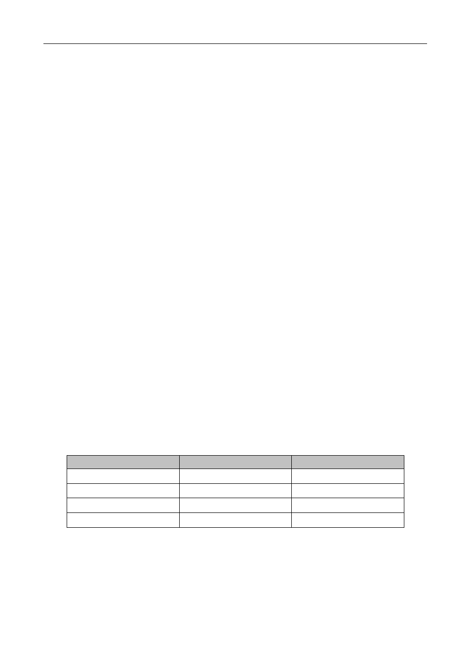
the mapping relationship for PC2 and PC4 to ports. The MAC table of switch will be:
MAC Address
Port number
Entry added by
00-01-11-11-11-11
1/0/5
Dynamic learning
00-01-22-22-22-22
1/0/5
Static configuration
00-01-33-33-33-33
1/0/12
Dynamic learning
00-01-44-44-44-44
1/0/12
Static configuration
1. Forward data according to the MAC table
If PC1 sends a message to PC3, the switch will forward the data received on port 1/0/5 from port1/0/12.
2. Filter data according to the MAC table
If PC1 sends a message to PC2, the switch, on checking the MAC table, will find PC2 and PC1 are in the
same physical segment and filter the message (i.e. drop this message).