PLANET XGS3-24042 User Manual
Page 316
38-12
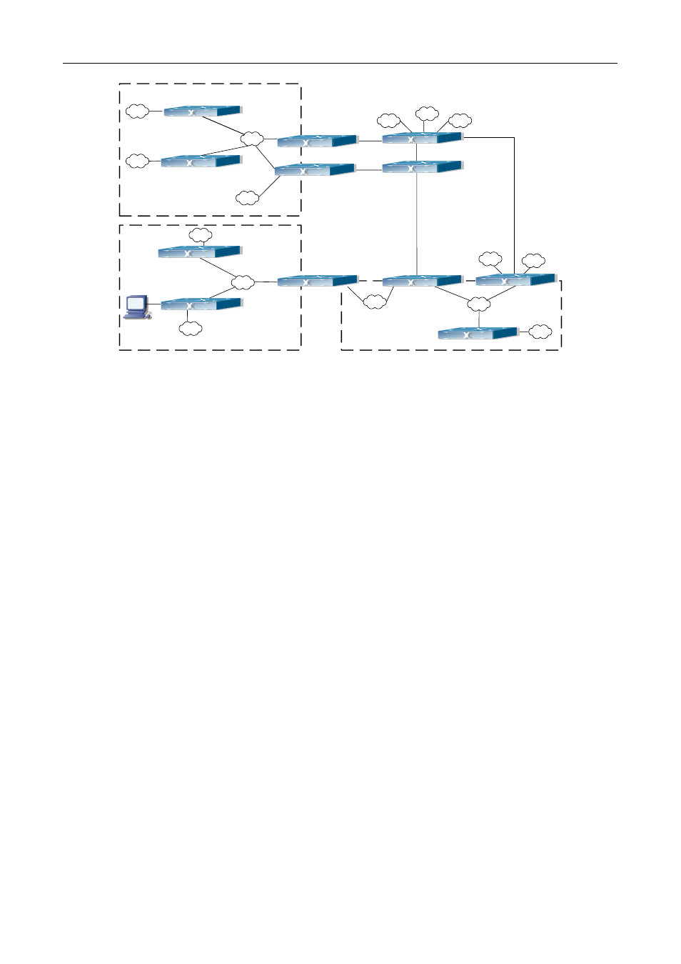
Figure 38-2 Typical complex OSPF autonomous system
This scenario is a typical complex OSPF autonomous system network topology. Area1 include network N1-N4
and layer3 SwitchA-SwitchD, area2 include network N8-N10, host H1 and layer3 SwitchH, area3 include
N5-N7 and layer3 SwitchF, SwitchG SwitchA0 and Switch11, and network N8-N10 share a summary route
with host H1(i.e. area3 is defined as a STUB area). Layer3 SwitchA, SwitchB, SwitchD, SwitchE, SwitchG,
SwitchH, Switch12 are in-area layer3 switches, SwitchC, SwitchD, SwitchF, Switch10 and Switch11 are edge
layer3 switches of the area, SwitchD and SwitchF are edge layer3 switches of the autonomous system.
To area1, layer3 switches SwitchA and SwitchB are both in-area switches, area edge switches SwitchC and
SwitchD are responsible for reporting distance cost to all destination outside the area, while they are also
responsible for reporting the position of the AS edge layer3 switches SwitchD and SwitchF, AS exterior
link-state advertisement from SwitchD and SwitchF are flooded throughout the whole autonomous system.
When ASE LSA floods in area 1, those LSAs are included in the area 1 database to get the routes to network
N11 and N15.
In addition, layer3 SwitchC and SwitchD must summary the topology of area 1 to the backbone area (area 0,
all non-0 areas must be connected via area 0, direct connections are not allowed), and advertise the networks
in area 1 (N1-N4) and the costs from SwitchC and SwitchD to those networks. As the backbone area is
required to keep connected, there must be a virtual link between backbone layer3 Switch10 and Switch11.
The area edge layer3 switches exchange summary information via the backbone layer3 switch, each area
edge layer3 switch listens to the summary information from the other edge layer3 switches.
Virtual link can not only maintain the connectivity of the backbone area, but also strengthen the backbone
area. For example, if the connection between backbone layer3 SwitchG and Switch10 is cut down, the
backbone area will become incontinuous. The backbone area can become more robust by establishing a
virtual link between backbone layer3 switches SwitchF and Switch10. In addition, the virtual link between
SwitchF and Switch10 provide a short path from area 3 to layer3 SwitchF.
Take area 1 as an example. Assume the IP address of layer3 SwitchA is 10.1.1.1, IP address of layer3
Area3
Area2
Area1
N3
N1
N8
N5
N6
N9
N10
N4
N2
N15
N14
N7
N11
Area0
SwitchA
SwitchB
SwitchC
SwitchD
SwitchE
SwitchF
SwitchI
SwitchL
SwitchK
SwitchJ
SwitchG
SwitchH
N12
N13