PLANET XGS3-24042 User Manual
Page 604
67-5
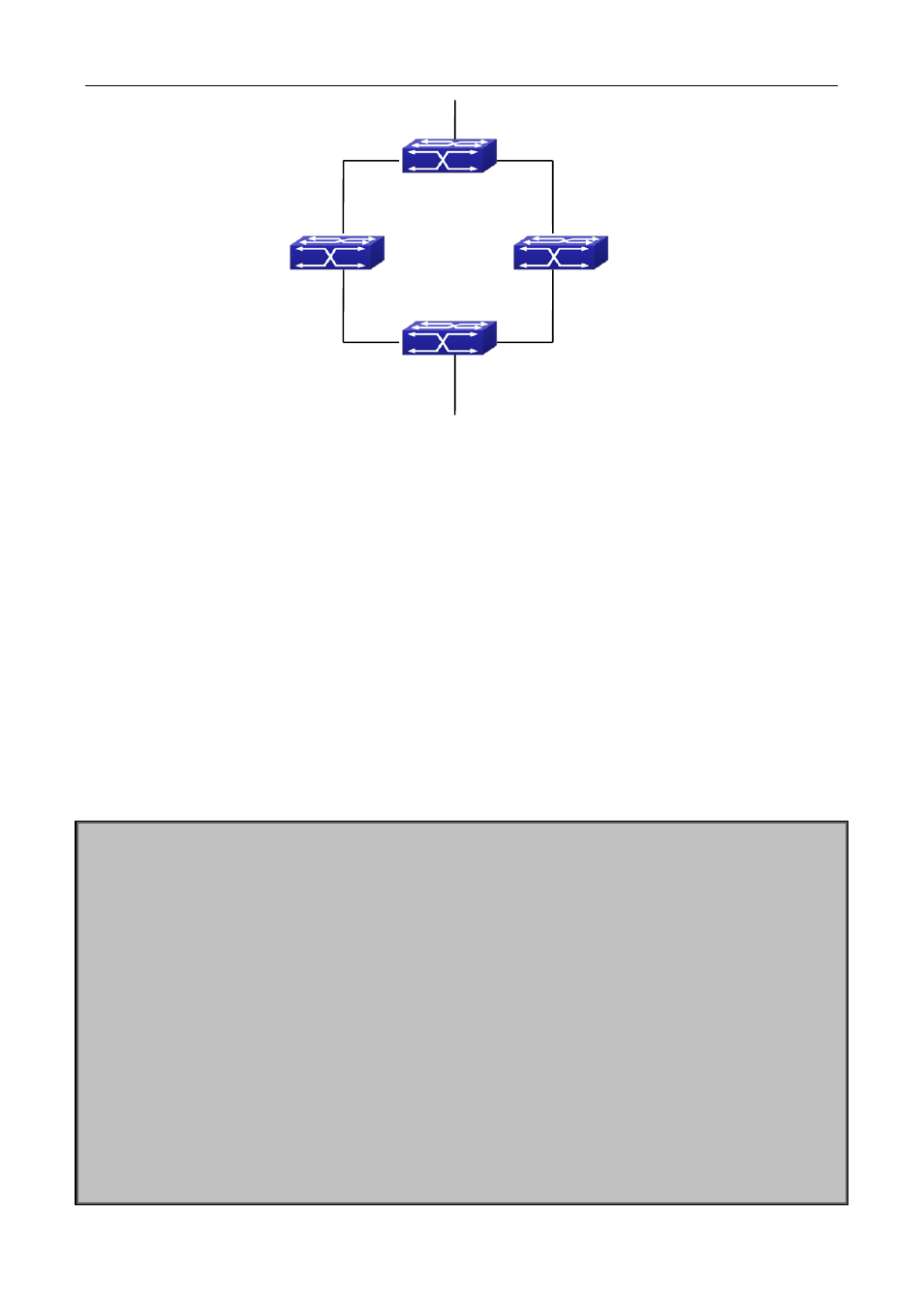
Figure 67-3 ULPP typical example1
The above topology is the typical application environment of ULPP protocol.
SwitchA has two uplinks, they are SwitchB and SwitchC. When any protocols are not enabled, this topology
forms a ring. For avoiding the loopback, SwitchA can configure ULPP protocol, the master port and the slave
port of ULPP group. When both master port and slave port are up, the slave port will be set as standby state
and will not forward the data packets. When the master port is down, the slave port will be set as forwarding
state and switch to the uplink. SwitchB and SwitchC can enable the command that receives the flush packets,
it is used to associate with ULPP protocol running of SwitchA to switch the uplink immediately and reduce the
switch delay.
When configuring ULPP protocol of SwitchA, first, create a ULPP group and configure the protection VLAN of
this group as vlan10, then configure interface Ethernet 1/0/1 as the master port, interface Ethernet 1/0/2 as
the slave port, the control VLAN as 10. SwitchB and SwitchC configure the flush packets that receive ULPP.
SwitchA configuration task list:
Switch(Config)#vlan 10
Switch(Config-vlan10)#switchport interface ethernet 1/0/1; 1/0/2
Switch(Config-vlan10)#exit
Switch(Config)#spanning-tree mst configuration
Switch(Config-Mstp-Region)#instance 1 vlan 10
Switch(Config-Mstp-Region)#exit
Switch(Config)#ulpp group 1
Switch(ulpp-group-1)#protect vlan-reference-instance 1
Switch(ulpp-group-1)#control vlan 10
Switch(ulpp-group-1)#exit
Switch(Config)#interface ethernet 1/0/1
Switch(config-If-Ethernet1/0/1)# ulpp group 1 master
Switch(config-If-Ethernet1/0/1)#exit
Switch(Config)#interface Ethernet 1/0/2
Switch(config-If-Ethernet1/0/2)# ulpp group 1 slave
SwitchB E1/1
SwitchD
SwitchA
E1/2 SwitchC
E1/2
E1/1