2 ) holding, 3 ) aborting – Yaskawa JAPMC-MC2300 User Manual
Page 150
7.2 Motion Command Details
7.2.2 External Positioning (EX_POSING)
7-10
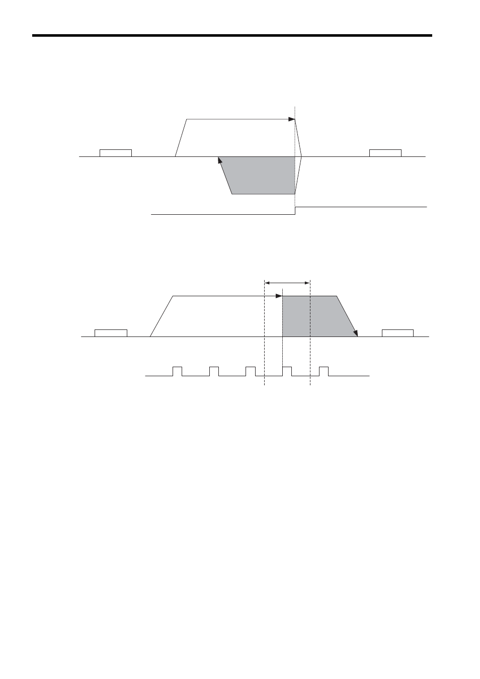
When the sign of the External Positioning Final Travel Distance is opposite to the direction of positioning to the
target position, the axis will be decelerated to a stop and then starts moving in the reverse direction as illustrated
below.
While the latch zone setting is enabled, any external input signal out of the latch enabled zone is ignored.
In this case, the position is latched when the first external signal is input in the latch enabled zone, and the axis
moves from this latched position for the external positioning move distance for positioning.
( 2 ) Holding
Axis travel can be stopped during command execution and then the remaining travel can be restarted. A command is
held by setting the Holds A Command bit (OW
09, bit 0) to 1.
• Set the Holds A Command bit (OW
09, bit 0) to 1. The axis will decelerate to a stop.
• When the axis has stopped, the Command Hold Completed bit (IW
09, bit 1) will turn ON.
• Reset the Holds A Command bit (OW
09, bit 0) to 0.
The command hold status will be cleared and the remaining portion of the operation will be restarted.
( 3 ) Aborting
Axis travel can be stopped during command execution and the remaining travel canceled by aborting execution of a
command. A command is aborted by setting the Interrupt A Command bit (OW
09, bit 1) to 1.
• Set the Interrupt A Command bit (OW
09, bit 1) to 1. The axis will decelerate to a stop.
• When the axis has stopped, the remain travel will be canceled and the Positioning Completed bit (IW
0C,
bit 1) will turn ON.
• The positioning will restart if the Interrupt A Command bit (OW
09, bit 1) is reset to 0 during abort pro-
cessing.
• This type of operation will also be performed if the motion command is changed to NOP during axis move-
ment.
<External Input Signal>
EXT (pin No. 36) or
ZERO (pin No. 18) or
Phase-C signal
Speed Reference Setting
(OL
10)
External Positioning
Final Travel Distance
(OL
46)
N-OT
(DI_4)
P-OT
(DI_3)
Speed Reference Setting
(OL
10)
<External Input Signal>
EXT (pin No. 36) or
ZERO (pin No. 18) or
Phase-C signal
Latch Zone Upper Limit Setting (OL
2C)
Latch Zone Lower Limit Setting (OL
2A)
External Positioning
Final Travel Distance
Latch enabled zone
N-OT
(DI_4)
P-OT
(DI_3)
(OL
46)